


2. Wiring and Connection
2 - 45
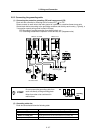
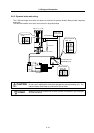
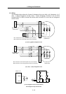
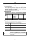
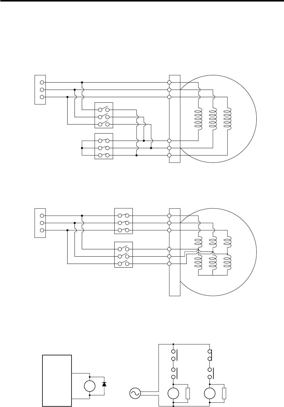
(3) Wiring
The illustration below shows the 2 types of changeover that occur after a coil changeover, (a) Y
(star) – ∆ (delta) changeover, and (b) Y (star) – Y (star) changeover. As shown in (c), one of the
contactors (MC1 or MC2) is turned ON and the other is turned OFF at all of the coil changeover
control circuits.
U
V
W
X
Y
Z
U
V
W
MC2
MC1
S
p
indle moto
r
Spindle drive unit
terminal block
MC1: Contactor to connect low-speed coil (Y-connection)
MC2: Contactor to connect high-speed coil (∆-connection)
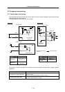
(a) Y (star) - ∆ (delta) changeover circuit
U1
V1
W1
U2
V2
W2
U
V
W
MC1
Spindle motor
Spindle drive unit
terminal block
MC2
MC1: Contactor to connect low-speed coil (1st Y-connection)
MC2: Contactor to connect high-speed coil (2nd Y-connection)
(b) Y (star) - Y (star) changeover circuit
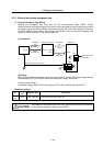
(c) Coil changeover control circuit (common)
Coil changeover relay control circuit
CN9-8
CN9-10
MDS-C1-SP
RA
MC1 SK
MC2
RA
S
T
MC2 SK
MC1
RA