


6. Troubleshooting
6 - 24
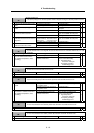
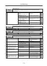
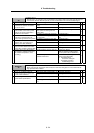
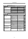
Alarm No.
43
Feedback error 2
With the servo, an excessive error was detected in the position data for the motor side detector and
machine side detector. With the spindle, an error was detected in the encoder feedback signal.
Investigation details Investigation results Remedies SV SP
The connector is disconnected (or
loose).
Correctly install. 1 Check whether the drive unit
connectors or detector connectors
are disconnected.
The connector is not disconnected. Investigate item 2.
{
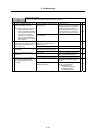
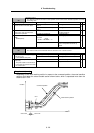
The cables are wired near each
other. (Noise is entering from the
power cable.)
Improve the cable wiring. 2 Is the detector cable wired in the
same conduit as the motor's power
cable or are the two cables laid in
parallel near each other?
The wires are sufficiently separated. Investigate item 3.
{
The motor FG wire is grounded on
the motor side.
Connect together on the drive unit
side.
3 Is the motor FG wire connected only
to the drive unit which drives it?
(Is the motor grounded to one point?)
The motor is grounded to one point. Investigate item 4.
{
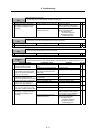
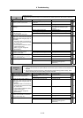
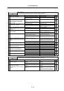
There is a connection fault. Replace the detector cable. 4 Turn the power OFF, and check the
detector cable connection with a
tester. (Is the cable shielded?)
The connection is normal. Investigate item 5.
{
The alarm is on the drive unit side. Replace the drive unit. 5 Connect to another normal axis drive
unit, and check whether the fault is
on the drive unit side or detector side.
The alarm is on the detector side. Investigate item 6.
{
No abnormality is found in particular. Replace the detector.
(With the absolute position system,
the zero point must be established.)
6 Check if there is any abnormality in
the detector's ambient environment.
(Ex. Ambient temperature, noise,
grounding)
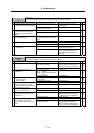
An abnormality was found in the
ambient environment.
Take remedies according to the
causes of the abnormality.
Ex. High temperature:
Check the cooling fan.
Incomplete grounding:
Additionally ground.
{
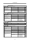
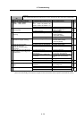
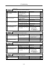
Alarm No.
44
C-axis changeover alarm
When using the coil changeover control motor, the mode was changed to C-axis control while the
high-speed coil was selected.
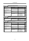
Investigation details Investigation results Remedies SV SP
High-speed coil is selected (bitD = 0) Correct the sequence. 1 Check the coil selected with the
spindle control input 3, bitD for the
C-axis control command.
Low-speed coil is selected (bitD= 1) Investigate item 2.
{
Coil changeover valid (SP034/bit2 =
1)
Correctly set the parameter. 2 Is coil changeover validated for the
special motor specifications?
Coil changeover invalid (SP034/bit2
= 0)
Replace the drive unit.
{