


1. Installation
1 - 21
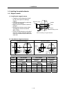
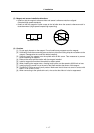
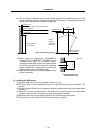
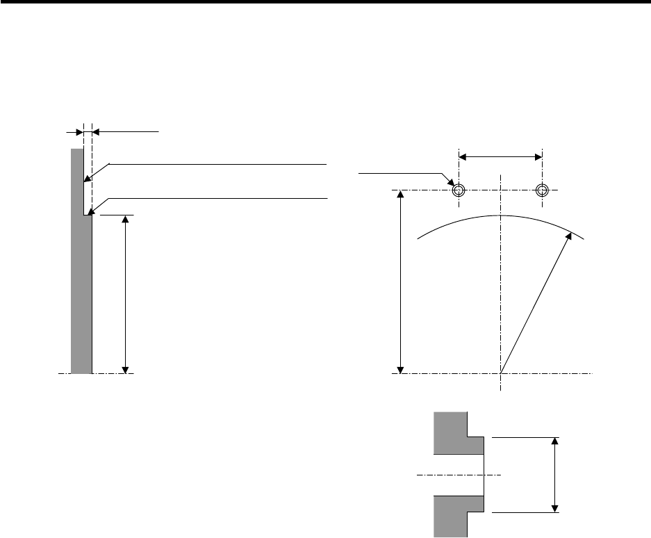
[8] With the sensor installation seat's R section butted against the notched fitting section, fix the
sensor installation seat with a mounting screw (M5 x 0.8 screws). A locking agent should be
applied on the mounting screw before it is tightened.
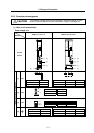
[9] When using the specifications (TS1860N2770,
TS1860N2776, TS1860N2183, TS1860N2187) with
installation plate (ring) for the sensor section,
provide a notched fitting section on the machine side
as shown on the right, and fit the sensor installation
plate's ø108H5 here. The gap does not need to be
adjusted when using the installation plate.
[10] Make sure that force is not constantly applied on the
sensor's lead wires.
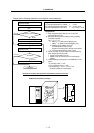
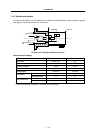
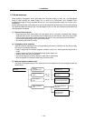
(3) Installing the PCB section
[1] Install the PCB where it will not be subject to water or oil, etc.
[2] Drill two ø11mm or smaller installation seats, and fix the PCB with pan head screws (M5 × 0.8
screws).
[3] Provide a space of 25mm from the installation surface to treat the lead wires for the intermediate
connector.
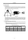
[4] Select the minimum required length for the lead wires from the sensor to the intermediate
connector, and wire them as far away from other power wires as possible.
[5] Make sure that force is not constantly applied on the PCB lead wire connections.
[6] The check pins on the PCB could break if excessive force is applied.
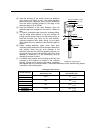
Installing the sensor with
Installation plate (ring)
ø 108
-0.005
-0.020
[
Unit: mm
]
3.5mm or less
Butt the R section of the sensor installation seat
a
g
ainst here
Butt the back side of the sensor installation
seat against here
Notched section's
outer diameter
2-M5
×
0.8 screw
Notched section's
outer diameter
29mm
Outline
drawing
designated
dimensions
Shape of notched fitting section