


Appendix 1. Cable and Connector Specifications
A1 - 2
Appendix 1-1 Selection of cable
Appendix 1-1-1 Cable wire and assembly
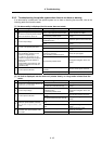
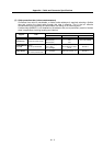
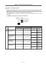
(1) Cable wire
The following shows the specifications and processing of the wire used in each cable. Manufacture
the cable using the following recommended wire or equivalent parts.
Wire characteristics Recommended
wire model
(Cannot be directly
ordered from
Mitsubishi
Electric Corp.)
Finished
outside
diameter
Sheath
material
No. of
pairs
Config-
uration
Conductor
resistance
Withstand
voltage
Insulation
resistance
Heat
resistant
temperature
Applica-
tion
UL20276 AWG28
10pair
6.1mm PVC 10
7
strands/
0.13mm
222Ω/km
or less
AC350/ 1min
1MΩ/km
or more
80°C
NC unit
communi-
cation cable
A14B2343 (Note 1) 7.2mm PVC 6
40
strands/
0.08mm
105Ω/km
or less
AC500/ 1min
1500MΩ/k
m or more
105°C
Detector
cable
2
(0.3 mm
2
)
60
strands/
0.08mm
63Ω/km
or less
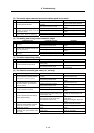
TS-91026 (Note 2) 11.6mm PVC
10
(0.2 mm
2
)
40
strands/
0.08mm
95Ω/km
or less
AC750V/
1min
60MΩ/km
or more
60°C
Detector
cable
(Cable length:
20m or more)
(Note 1) Junko Co. (Dealer: Toa Denki)
(Note 2) BANDO ELECTRIC WIRE (http: //www.bew.co.jp)
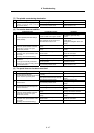
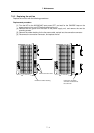
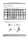
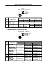
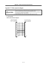
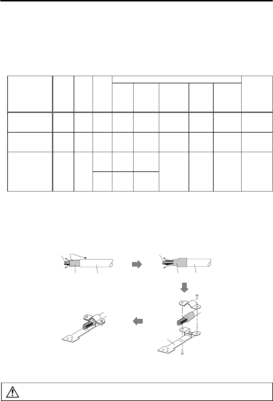
(2) Cable assembly
Assemble the cable as shown in the following drawing, with the cable shield wire securely
connected to the ground plate of the connector.
Ground plate
Shield
(external conductor)
Sheath
Shield
(external conductor)
Sheath
Core wire
Core wire
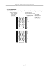
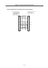
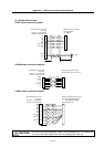
CAUTION
Do not mistake the connection when manufacturing the detector cable. Failure to
observe this could lead to faults, runaway or fires.