


1. Installation
1 - 19
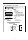
1-4-3 Spindle end PLG
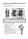
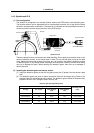
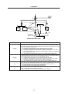
(1) Part configuration
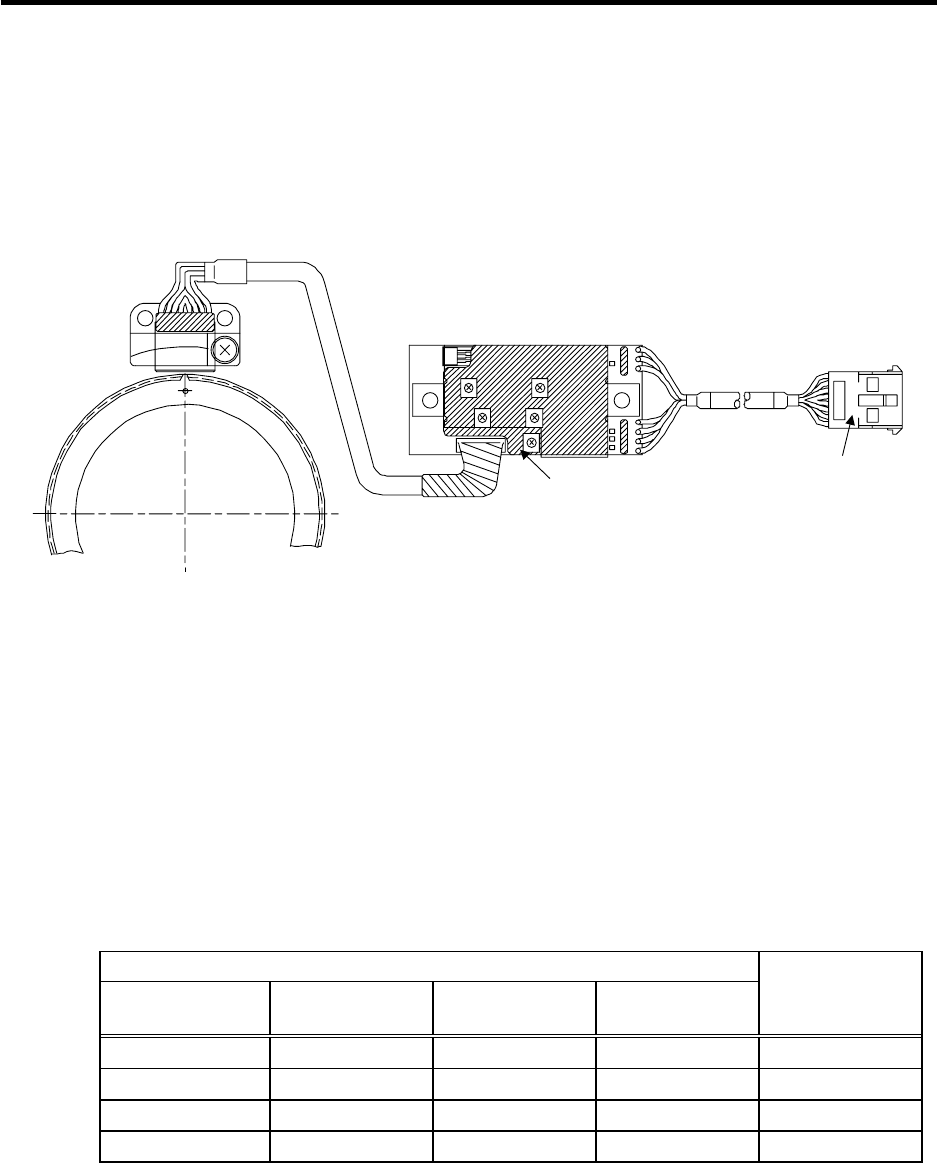
The detector is configured of an encoder (Sensor section and PCB section) and detection gears.
The encoder section can be separated with an intermediate connector, but a type with the same
serial No. must be used in combination. The serial No. is indicated on the intermediate connector of
the sensor section and the output connector of the PCB section.
G
B
Z
A
VR1
VR2
VR3
VR4
VR5
Detection
gears
Sensor section
PCB section
Intermediate
connecto
r
Output connector
Serial No. indication
Encoder
Spindle end PLG
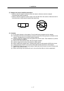
These are precision parts, and require care when handling. Do not apply an excessive force on the
sensor's detection surface, as this could result in faults. Do not pull and apply a load on the lead
wires. Make sure that foreign matters (iron chips, etc.) do not get on the sensor's detection surface
or detection gears. If any foreign matter should get on these parts, carefully remove while taking
care not to damage the parts. When handling the detection gears, take care not to damage or
deform the teeth.
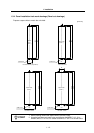
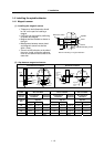
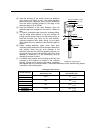
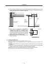
(2) Installing the detection gears and sensor section
[1] Install the detection gears so that the first gear's teeth side (Z phase) face the sensor's lead
side.
[2] The detection gears and shaft or sleeve should be fixed with shrinkage fitting. Refer to the
following table for the shrinkage fitting values. The detection gears should be heated evenly
between 120 and 150°C using an electric furnace, etc.
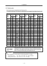
Detection gear shrinkage fitting values
Detection gear specifications
Part type
No. of teeth
Outer diameter
(mm)
Inner diameter
(mm)
Shrinkage fitting
(mm)
MU1450N2137 128 ø52 ø40 0.02 to 0.04
MU1450N2730 180 ø72.8 ø55 0.03 to 0.055
MU1450N2236 256 ø103.2 ø80 0.03 to 0.055
MU1450N2534 512 ø205.6 ø140 0.05 to 0.085