


3. Setup
3 - 60
Standard specifications
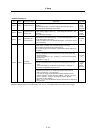
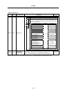
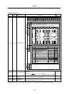
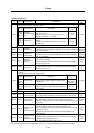
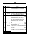
No. Abbrev. Parameter name Explanation
Setting range
(Unit)
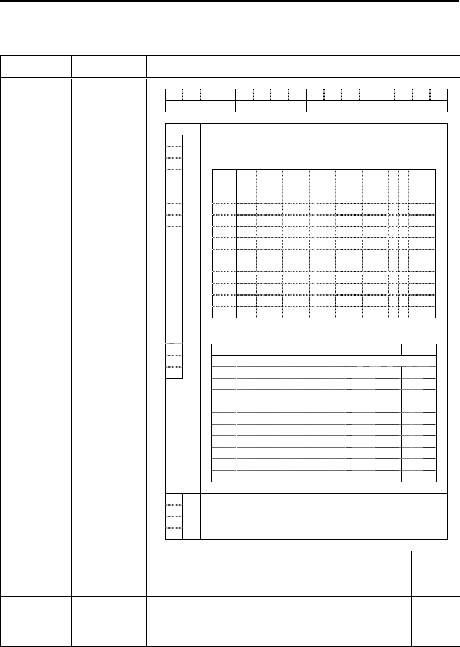
F E D C B A 9 8 7 6 5 4 3 2 1 0
amp rtyp ptyp
bit Explanation
0
1
When the CN4 connector of the drive unit and the power supply are
connected, setting below is necessary.
2 To validate the external emergency stop function, add 40h.
3 Setting 0x 1x 2x 3x 4x 5x 6x 7x 8x
4
ptyp
x0
Not
used
CV-300
5 x1 CV-110 CR-10
6 x2 CV-220 CR-15
7 x3 CR-22
x4 CV-3
7
CR-37
x5 CV-150
MDS-B-
CVE-450
MDS-B-
CVE-550
x6 CV-5
5
CV-260 CR-55
x7 CV-370
x8 CV-7
5
CR-75
x9 CV-185 CR-90
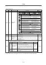
8
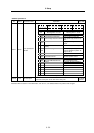
Set the regenerative resistor type when MDS-A-CR is used.
9
Setting Regenerative resistor model name Resistance value Capacity
A
0 MDS-C1-CV (Setting when using power supply regeneration)
B
rtyp
1 GZG200W260HMJ
26
Ω
80W
2
GZG300W130HMJ×2
26
Ω
150W
3 MR-RB30
13
Ω
300W
4 MR-RB50
13
Ω
500W
5 GZG200W200HMJ × 3
6.7
Ω
350W
6 GZG300W200HMJ × 3
6.7
Ω
500W
7 R-UNIT-1
30
Ω
700W
8 R-UNIT-2
15Ω
700W
9 R-UNIT-3
15Ω
2100W
A to F No setting
C Always set "0".
D
E
amp
F
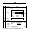
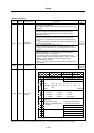
SV036 PTYP*
Power supply type
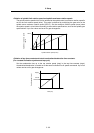
Set “the motor inertia + motor axis conversion load inertia” in respect to the
motor inertia.
Jl+Jm Jm Motor inertia
SV037 JL
Load inertia scale
SV037(JL) =
Jm
×100
Jl Motor axis conversion load inertia
0 to 5000
(%)
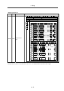
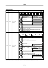
SV038 FHz1
Notch filter
frequency 1
Set the vibration frequency to suppress if machine vibration occurs.
(Valid at 36 or more) When not using, set to “0”.
0 to 3000
(Hz)
SV039 LMCD
Lost motion
compensation
timing
Set this when the lost motion compensation type2 timing doest not match.
Adjust by increasing the value by 10 at a time.
0 to 2000
(ms)
Parameters with an asterisk * in the abbreviation, such as PC1*, are validated with the NC power turned ON again.