


Appendix 1. Cable and Connector Specifications
A1 - 10
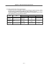
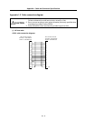
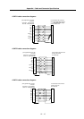
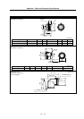
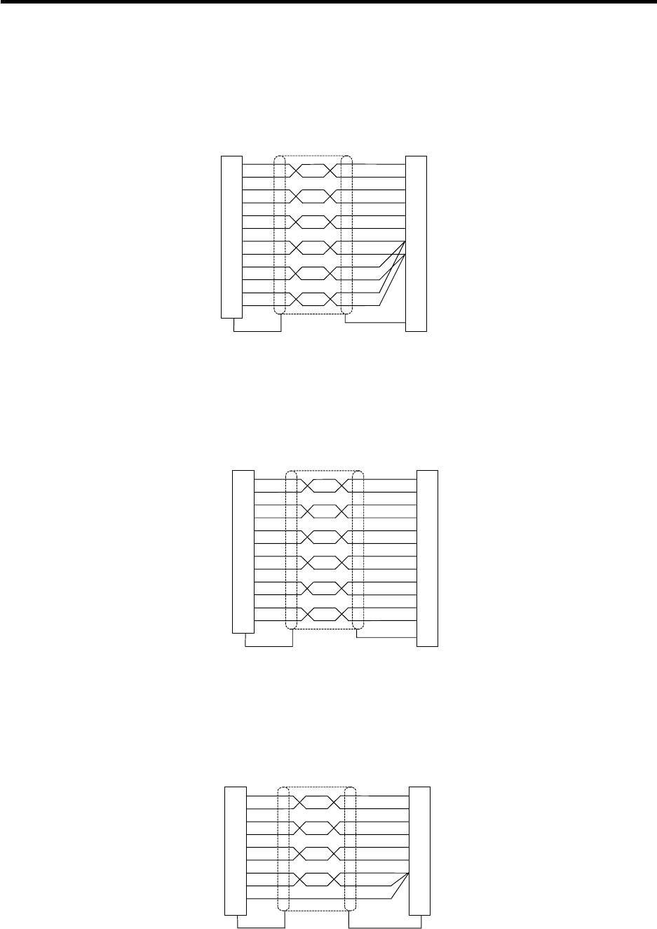
<CNP7A cable connection diagram>
F
L
G
M
S
T
H
K
E
2
12
3
13
4
14
10
1
19
11
20
15
C
A
CA
*
CB
CB
*
CZ
CZ
*
P5(+5V)
LG
P5(+5V)
LG
P5(+5V)
LG
B24-9
(CN7) Spindle drive unit side
connector
Connector: 10120-3000VE
Shell kit: 10320-52F0-008
C-axis detector side connector
Plug: MS3106B20-29S (Straight)
MS3108B20-29S (Angle)
Clamp: MS3057-12A
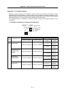
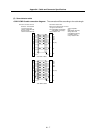
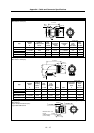
<CNP7B cable connection diagram>
2
12
3
13
4
14
10
1
19
11
20
15
C
A
CA
*
CB
CB
*
CZ
CZ
*
P5(+5V)
LG
P5(+5V)
LG
P5(+5V)
LG
B24-9
1
11
2
12
3
13
7
9
8
18
17
19
20
(CN7) Spindle drive unit side
connector
Connector: 10120-3000VE
Shell kit: 10320-52F0-008
C-axis detector side connector
Housing: 69176-020
Pin: 48235-000
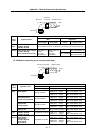
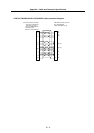
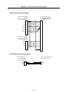
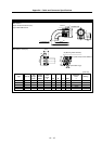
<CNP7H cable connection diagram>
2
12
3
13
4
14
1
11
15
C
A
CA
*
CB
CB
*
CZ
CZ
*
LG
LG
LG
1
2
3
4
5
6
7
(CN7) Spindle drive unit side
connector
Connector: 10120-3000VE
Shell kit: 10320-52F0-008
C-axis detector side connector
Housing: JAC-15P
Pin: J-SP1140