


5. Spindle Adjustment
5 - 29
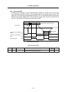
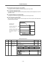
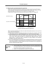
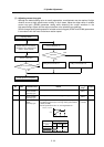
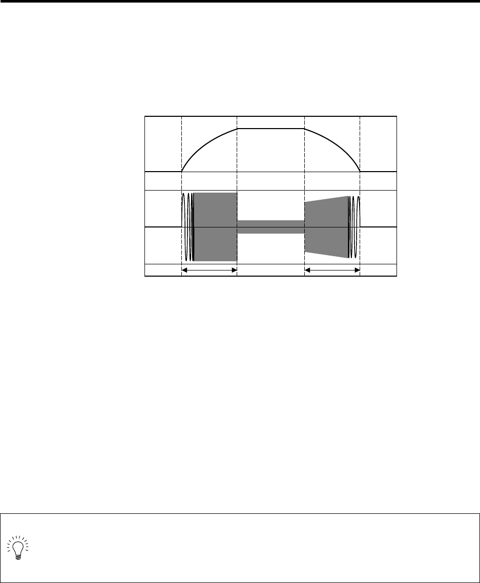
(2) Measuring the acceleration/deceleration waveforms
Measure the acceleration/deceleration waveforms by using the spindle drive unit's D/A output
function and check if theoretical acceleration/deceleration time is within ±15%. Refer to "5-1 D/A
output specifications for spindle drive unit" for details on D/A output functions.
Phase current FB output can be measured by the waveform for either U or V phase FB.
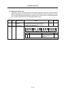
When acceleration/deceleration time does not match the theoretical value (an error rate 15% or
more), check the following items.
[1] There may be an error in calculating load inertia for the motor axis conversion used when
calculating the theoretical acceleration/deceleration time. Check the load inertia again.
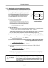
[2] When acceleration time is long and deceleration time is short, friction torque is thought to be
large. Check load meter value at the maximum speed (spindle monitor screen). If the load is
10% or more, friction torque is thought to be relatively large. Mechanical friction, such as
bearing friction or timing belt friction, is assumed to be large. Measure the acceleration/
deceleration time again following trial run.
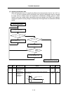
[3] Even if the problems above are not found, when acceleration/deceleration time does not match,
there may be a possibility of using spindle motor and spindle drive unit that are not specified, or
using wrong parameters. Check the spindle motor type and spindle drive unit type again, as
well as the spindle parameter settings.
POINT
1. There are cases where acceleration/deceleration waveforms change depending
on the spindle temperature. Check the waveforms when the spindle temperature
is high (after continuous operation) and when it is low.
2. Conduct "3-5 Initial adjustment of spindle PLG" beforehand.
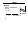
Speedometer output [V]
Acceleration/deceleration waveforms of spindle motor
0
4.0
2.5
1.0
U(V) phase current FB output [V]
Acceleration time: ta Deceleration time: td