5. Spindle Adjustment
5 - 45
[2] Speed loop gain adjustment
In the same manner as for the position loop gain, a speed loop gain can be set separately from
the one used during deceleration for a operation that begins from the orientation completed ON
status, following orientation deceleration control. Although the servo lock rigidity can be
improved by increasing the speed loop gain during stop, vibration tends to be generated.
To change the post-orientation speed loop gain, enable a gain change by SP097/bitC=1
parameter setting, then set the desired speed loop proportional gain magnification and integral
gain magnification. The proportional and integral gains should be increased at the same rate,
and should be decreased if vibration occurs.
The effective speed loop gains are common to all coils, and are calculated using the formulas
shown below. If a magnification setting of "0" is set, a "256" setting is adopted.
SP227
Effective speed loop proportional gain = SP098 ×
256
SP228
Effective speed loop integral gain = SP099 ×
256
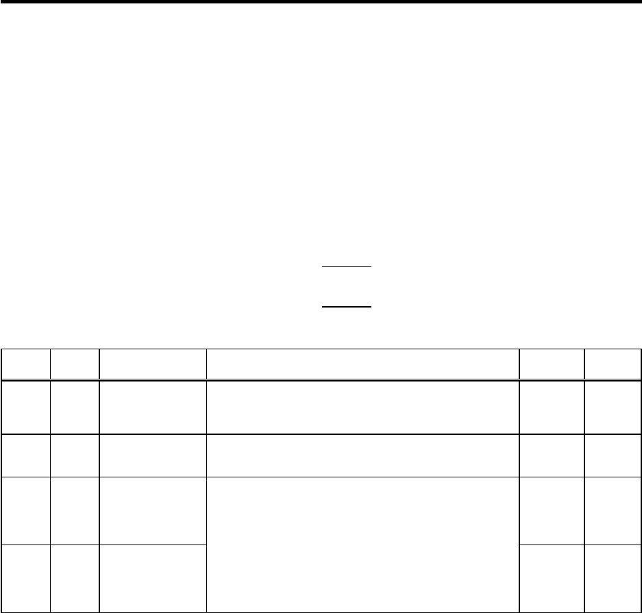
No. Abbr. Parameter name Details
Setting
range
Standard
SP098 VGOP* Speed loop gain
proportional term in
orientation control
mode
Set the speed loop proportional gain in orientation control mode.
When the gain is increased, rigidity is improved in the
orientation stop but vibration and sound become larger.
0 to 1000 63
SP099 VGOI* Orientation control
mode speed loop
gain integral term
Set the speed loop integral gain in orientation control mode. 0 to 1000 60
SP227 OXVKP Speed loop
proportional gain
magnification after
orientation
completed
0 to 2560
(1/256-fold)
0
SP228 OXVKI Speed loop
cumulative gain
magnification after
orientation
completed
If gain changeover is valid (SP097: SPEC0/bitC=1) during
orientation control, set the magnification of each gain changed
to after orientation completed.
0 to 2560
(1/256-fold)
0


