


1. Installation
1 - 16
1-4 Installing the spindle detector
1-4-1 Magnetic sensor
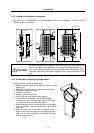
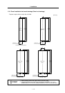
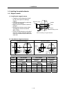
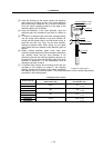
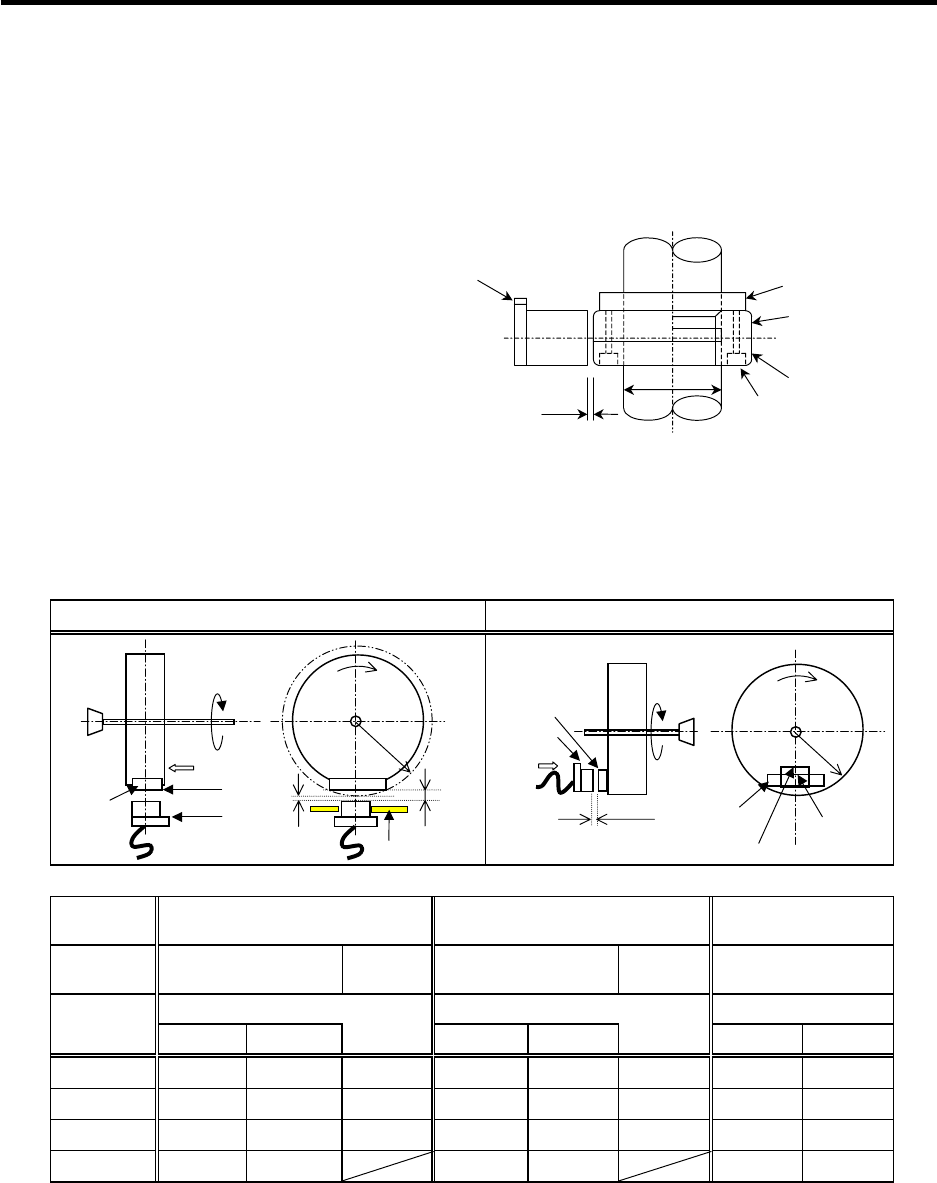
(1) Installing the magnetic sensor
• Tolerance to shaft dimension should
be "h6" on the part for installing a
magnet.
• 2-øG hole can be used for positioning
of spindle and magnet.
• Magnet shall be installed as shown to
the right.
• Misalignment between sensor head
and magnetic center line shall be
within ±2mm.
• There is an NS indication on the side of
the cover. Install so that the reference
notch on the sensor head comes to the
case side.
Gap
Reference notch
Reference drawing for magnet installation
G hole
h6
Spindle
Case
Cover
Spindle damping scre
w
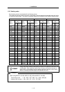
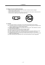
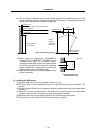
(2) Gap between magnet and sensor
Circumference installation
Horizontal installation
Magnet
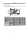
model
BKO-C1810H03 BKO-C1730H06 BKO-C1730H09
Installation
direction
Circumference
installation
Horizontal
installation
Circumference
installation
Horizontal
installation
Circumference
installation
Gap mm Gap mm Gap mm
R (Radius)
mm
Max. value Min. value Max. value Min. value Max. value Min. value
40 11.5±0.5 2.7±0.5 6.0±0.5 10.0±0.5 1.22±0.5 5.0±0.5 6.25±0.5 3.30±0.5
50 9.5±0.5 2.8±0.5 6.0±0.5 8.0±0.5 1.31±0.5 5.0±0.5 6.00±0.5 3.70±0.5
60 8.5±0.5 3.0±0.5 6.0±0.5 7.0±0.5 1.50±0.5 5.0±0.5 5.75±0.5 3.85±0.5
70 8.0±0.5 3.4±0.5 7.0±0.5 2.38±0.5 5.50±0.5 3.87±0.5
Reference
hole
Reference
notch
Magnet
Min. gap
Max. gap
Mounting plate
R
Direction of
rotation
NS
Spindle
Face A
Face A
Magnet
Gap
R
N
S
Spindle
Face B
Face B
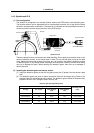
Reference
hole
Reference
hole
Reference
notch
Direction of
rotation
Reference
notch