


6. Troubleshooting
6 - 4
6-2 Protective functions list of units
6-2-1 List of alarms
When an alarm occurs, the servo drive unit will make the motor stop by the deceleration control or
dynamic brake. The spindle drive unit will coast to a stop or will decelerate to a stop. At the same time,
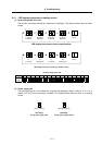
the alarm No. will appear on the NC monitor screen and with the LEDs on the front of the drive unit.
Check the alarm No., and remove the cause of the alarm by following this list.
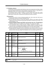
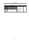
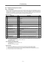
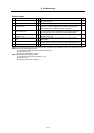
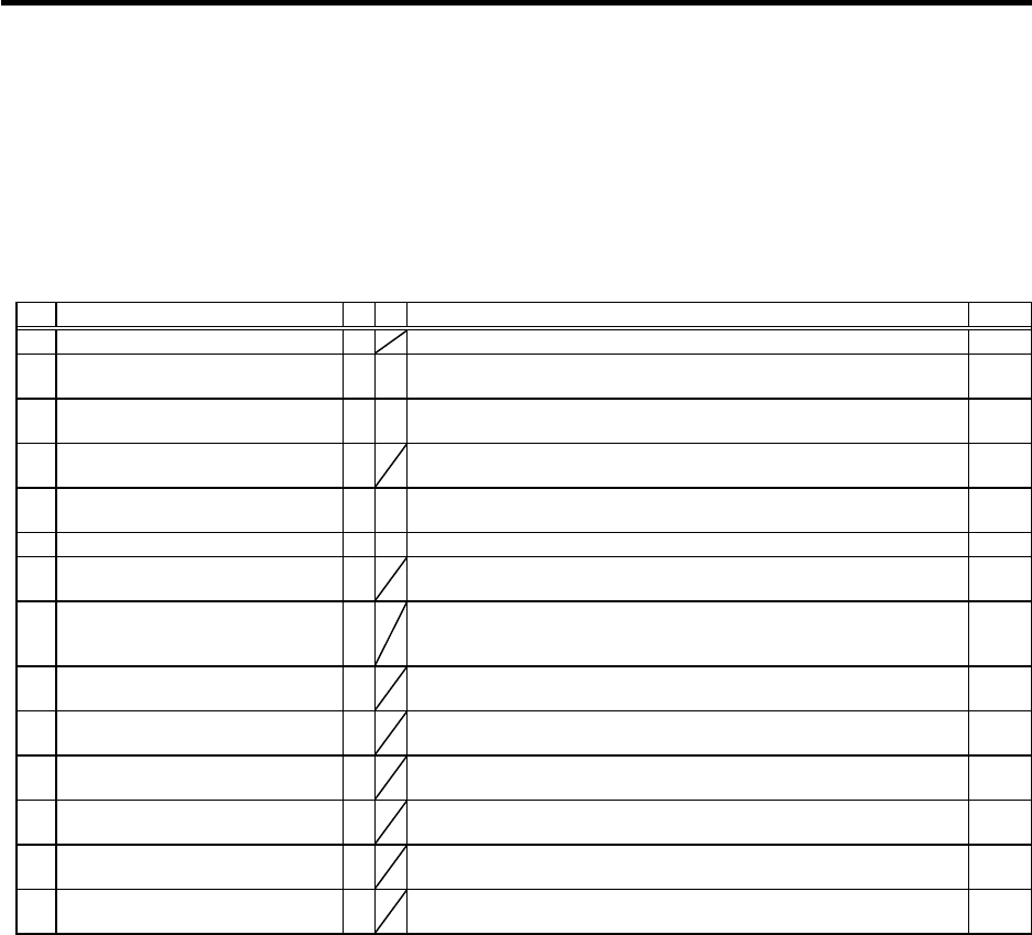
Drive unit alarm
No. Alarm name SV SP Alarm details Reset
11 Axis selection error
The axis No. selection switch setting is incorrect. AR
12 Memory error 1
A CPU or internal memory error was detected during the self-check at
power ON.
AR
13 Software processing error 1
§ §
The software process was not completed within the specified time.
(CPU1)
PR
14 Software processing error 2
{
The software process was not completed within the specified time.
(CPU2)
PR
16 Magnetic pole position detection
error
Creation of the initial magnetic pole, required for motor control, was not
completed.
PR
17 A/D converter error
An error was detected in the A/D converter for current FB detection. PR
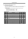
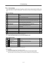
18 Motor side detector, initial
communication error
Initial communication with the motor end detector was not possible. PR
19 Synchronous control/detector
communication error
§
Initial communication with the master axis motor end detector was not
possible when the closed current command synchronous control was
set. Or, the communication was cut off.
PR
1A Machine side detector, initial
communication error
Initial communication with the linear scale or ball screw end detector
was not possible.
PR
1B Machine side detector, CPU error 1
A CPU initial error was detected with the linear scale or ball screw end
detector.
PR
1C Machine side detector,
EEPROM/LED abnormality
§
An error was detected in the data stored in the memory with the linear
scale. Or, LED deterioration was detected with the linear scale.
PR
1D Machine side detector, data error
§
A data error was detected with the linear scale or ball screw end
detector.
PR
1E Machine side detector, memory
error
§
An internal memory error was detected with the linear scale. PR
1F Machine side detector,
communication error
§
An error was detected in the communication data with the linear scale
or ball screw end detector. Or, the communication was cut off.
PR
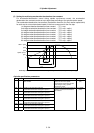
(Note 1) Motor stopping method applied when self-axis drive unit alarm occurs is indicated in SV for servo and in SP for spindle.
(Note 2) Servo (SV) alarm stopping method
{: Deceleration control (when SV048, SV055 or SV056 is set)
§: Dynamic brake stop
: Initial error (while motor is stopped)
(Note 3) Spindle (SP) alarm stopping method
{: Deceleration control (when SP038/bit0=1 is set)
§: Coast to a stop
: Initial error (while motor is stopped)
Resetting methods
NR : Reset with the NC RESET button. This alarm can also be reset with the PR and AR resetting conditions.
PR : Reset by turning the NC power ON again. This alarm can also be reset with the AR resetting conditions.
When the control axis is removed, this alarm can be reset with the NC RESET button. (Excluding alarms 32 and 37.)
AR : Reset by turning the servo drive unit power ON again.