


1. Installation
1 - 20
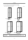
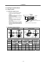
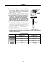
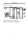
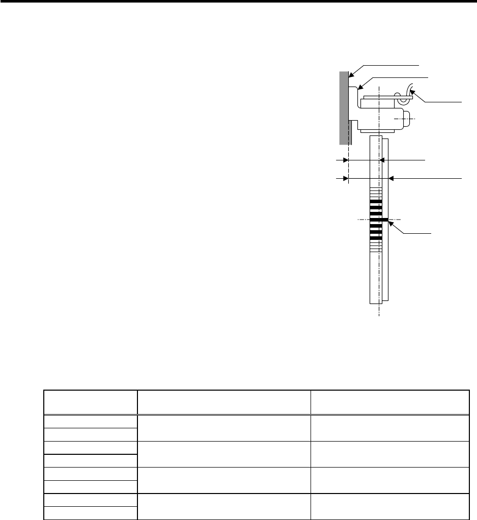
[3] Keep the deviation of the sensor center and detection
gear center to ±0.25mm or less. If the center deviation
cannot be directly measured, set so that the dimension
from the sensor installing surface to the edge of the
detection gears is 22.5±0.25mm.
[4] Keep the deflection of the outer diameter, when the
detection gears are installed on the shaft, to 0.02mm or
less.
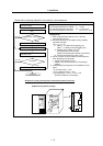
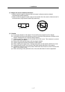
[5] To remove a detection gear fixed with shrinkage fitting,
use the screw holes opened in the axial direction for
pulling (two M5 screw holes or two M8 screw holes), or
push the end with a jig. Carry out this work carefully.
Applying excessive force when pulling out the gears
could cause the inner diameter of the detection gears to
deform.
[6] Before reusing detection gears which have been
removed, always measure the inner diameter dimensions,
and carefully check that the inner diameter is not
deformed, and that the sufficient tightening amount can
be secured. Do not reuse the detection gears if the inner
diameter is deformed, or if any abnormality such as
damage to the teeth is found.
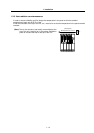
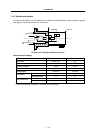
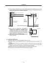
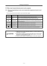
[7] A notched fitting section and mounting screw hole are
provided on the machine as shown in the following
drawing. Contact the R section of the sensor installation
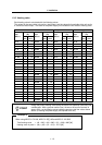
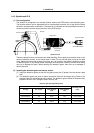
seat against this and, install the sensor. The outline dimensions of the notched fitting section
are shown in the following table.
Installing the sensor section
Encoder part type
Sensor installation seat's
R dimensions (mm)
Notched fitting section's
outer diameter (mm)
TS1860N2275 +0.200
TS1860N2276
R35.5 ø71
+0.180
TS1860N2777 +0.200
TS1860N2775
R45 ø90
+0.180
TS1860N2171 +0.200
TS1860N2174
R61 ø122
+0.175
TS1860N2571 +0.200
TS1860N2572
R112.5 ø225
+0.170
16.5mm
22.5mm
±.25mm
Sensor installation surface
Sensor installation seat
Lead wire
First tooth
Installing the detection gears