


5. Spindle Adjustment
5 - 52
(4) Adjusting the parameters
Adjust the following parameters while measuring the synchronous error between the servo and
spindle. The servo axis speed loop gain is valid for all control, so adjust the speed loop gain only
on the spindle side. Adjust mainly the lost motion compensation parameters on the servo side.
When these have already been adjusted when measuring the roundness, etc., they do not need to
be adjusted again. If the acceleration/deceleration is delayed for one of the axes, set the
acceleration feed forward gain for the delayed axis to compensate the synchronous delay.
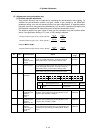
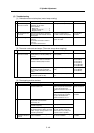
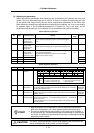
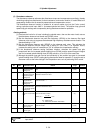
Spindle adjustment parameters
No. Abbr. Parameter name Details
Setting
range
Standard
SP194 VGTP* Synchronized
tapping control
speed loop gain
proportional term
Set the speed loop proportional gain in synchronized tapping
mode.
0 to 1000 63
SP195 VGTI* Synchronized
tapping control
speed loop gain
integral term
Set the speed loop integral gain in synchronized tapping mode.
0 to 1000 60
SP200 FFCI* Synchronized
tapping control
acceleration feed
forward gain (gear 1)
0
SP201 FFC2* (Gear 2) 0
SP202 FFC3* (Gear 3) 0
SP203 FFC4* (Gear 4)
Set the acceleration feed forward gain for selection of gear 000
during synchronized tapping.
This parameter should be used when an error of relative
position to Z-axis servo is large.
0 to 1000
(%)
0
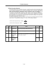
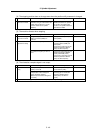
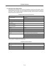
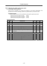
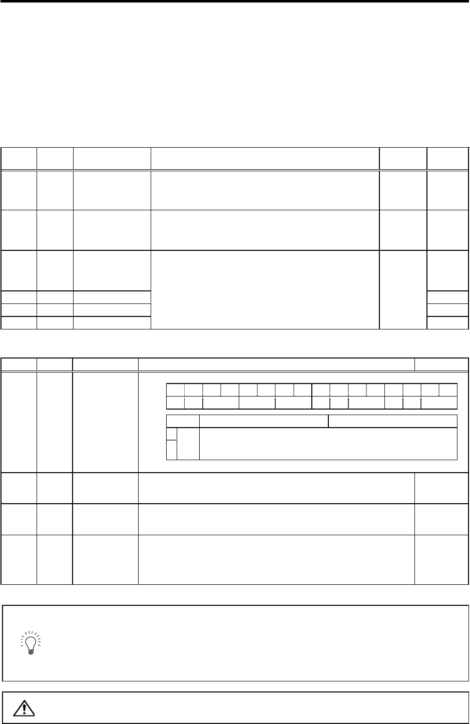
Spindle adjustment parameters
No. Abbr. Parameter name Details Setting range
FEDCBA98765 4 3 2 10
aflt zrn2 afse ovs lmc omr zrn3 vfct upc vcnt
bit Meaning when set to 0 Meaning when set to 1
8
Set the compensation amount with SV016 (LMC1) and SV041 (LMC2).
9
lmc
00: Lost motion compensation stop
01: Lost motion compensation type 1
10: Lost motion compensation type 2
11: Setting prohibited
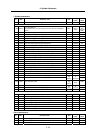
SV027 SSF1 Servo function
selection 1
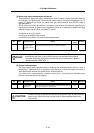
SV016 LMC1 Lost motion
compensation 1
Set the compensation amount based on the stall (rated) current of the motor.
The standard setting is double of the friction torque. Setting to "0" means the
compensation amount is zero.
-1 to 200
(Stall [rated]
current %)
SV041 LMC2 Lost motion
compensation 2
Set this with SV016 (LMC1) only when you wish to set the lost motion
compensation amount to be different depending on the command directions.
Normally, set to "0".
-1 to 200
(Stall [rated]
current %)
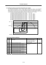
SV015 FFC Acceleration rate
feed forward gain
When a relative error in the synchronous control is large, apply this parameter
to the axis that is delaying. The standard setting value is "0". For the SHG
control, set to "100".
To adjust a relative error in acceleration/deceleration, increase the value by
50 to 100 at a time.
0 to 999
(%)
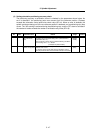
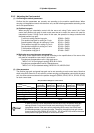
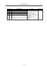
POINT
1. Stop the machine error compensation function (backlash compensation,
pitch error compensation, etc.) when measuring the synchronous error.
2. The servo's speed loop gain has an effect on all control, so do not adjust it
for synchronous tap. The spindle parameters are dedicated for synchronous
tap control, so improve the synchronization accuracy by adjusting the spindle
parameters when possible.
CAUTION
The above spindle parameters adjusted when adjusting the synchronous tap
are all validated when the NC power is turned ON again.