


1. Installation
1 - 15
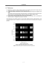
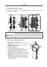
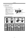
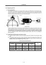
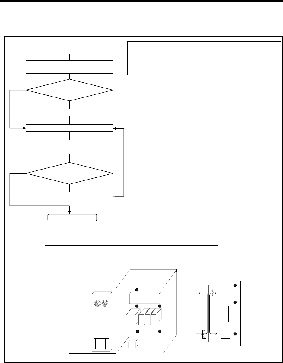
Please refer to following method for heat radiation countermeasures.
Heat
exchange
r
Unit
Flow of air
Flow of air
Relay, etc
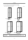
Examples of mounting and temperature measurement positions (reference)
z
Measurement position (example)
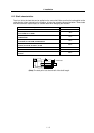
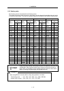
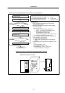
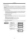
Calculate total heat radiation of each
mounted unit (W)
Comparison of W and W1
W ≤ W1
Collection of internal temperature rise
distribution data
Mounting design
Improvements
Completion
Selection of heat exchanger
Evaluation
W>W1
∆T≤10°C
∆T>10°C
Calculate cabinet’s cooling capacity
(W1)
<Hypothetical conditions>
(1) Average temperature in cabinet : T ≤ 55°C
(2) Cabinet peripheral temperature : Ta ≤ 0°C to 45°C
(3) Internal temperature rise value : ∆T =T–Ta
max= 10°C
<Supplement>
1) Refer to Specifications Manual, etc. for the heat
generated by each unit.
2) Enclosed cabinet (thin steel plate) cooling capacity
calculation equation
W1 = U × A × ∆T
U: 6W/m
2
×
°C (with internal agitating fan)
4W/m
2
× °C (without internal agitating fan)
A: Effective heat radiation area (m
2
)
(Heat dissipation area in panel)
Sections contacting other objects are excluded.
∆T: Internal temperature rise value (10°C)
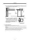
3) Points of caution for heat radiation countermeasures
when designing mounting state
• Layout of convection in panel
• Collect hot air at suction port in heat exchanger
cabinet.
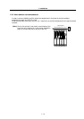
4) Understanding the temperature rise distribution in the
panel
∆T (average value) ≤ 10°C
∆T
max (maximum value) ≤ 15°C
R (inconsistency) = (∆T
max – ∆Tmin) ≤ 6°C
(Evaluate existence of heat spots)