


6. Troubleshooting
6 - 20
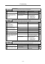
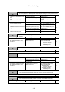
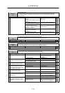
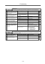
Alarm No.
37
Initial parameter error
An illegal parameter was detected in the parameters received from the NC at NC power ON.
"S02 initial parameter error ####" is displayed on the NC screen. #### indicates the incorrect
parameter No.
Investigation details Investigation results Remedies SV SP
SV001 to SV065 (M60S Series: 2201
to 2265)
SP001 to SP384 (M60S Series: 3201
to 3584)
Set the value within the designated
setting range.
1 Check the error parameter No.
SV101 (M60S Series: 2301)
The electronic gears are overflowing.
Check SV001, SV002 and SV018.
{ {
SV102 (M60S Series: 2302)
The absolute position detection
parameter is valid when OSE104 and
OSE105 are connected.
Absolute position control cannot be
used. To use, change to an absolute
position detector.
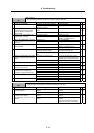
SV104 (M60S Series: 2304)
No SHG control operation is
provided.
SHG control cannot be used.
{
SV105 (M60S Series: 2305)
No adaptive filter option is provided.
The adaptive filter cannot be used.
{
(Note) Refer to "6-3-4 Parameter numbers at initial parameter error".
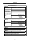
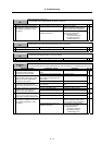
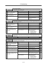
Alarm No.
38
Communication or protocol error 1 between NC and drive unit
An error was detected in the communication frame received from the NC.
Investigation details Investigation results Remedies SV SP
1 Check the alarm No. "34" items.
{ {
Alarm No.
39
Communication or protocol error 2 between NC and drive unit
An error was detected in the axis information data received from the NC.
Investigation details Investigation results Remedies SV SP
1 Check the alarm No. "34" items.
{ {
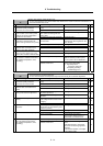
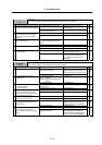
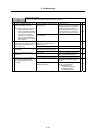
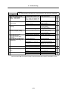
Alarm No.
3A
Overcurrent
An excessive current was detected in the motor drive current.
Investigation details Investigation results Remedies SV SP
Vibration is occurring.
• Set a filter.
• Lower the speed loop gain
(SV005).
1 Check whether vibration is occurring.
There is no vibration. Investigate item 2.
{
The setting is too large. Set an appropriate value. 2 The speed loop gain (SV005) setting
is larger than the standard value.
The setting is approximately the
same as the standard value.
Investigate item 3.
{
The setting is incorrect. Set the standard value. 3 Check the current loop gain.
(SV009, SV010, SV011, SV012)
The standard value is set. Investigate item 4.
{
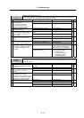
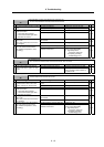
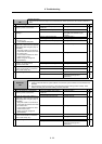
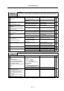
The power cable is short-circuited. Replace the motor power cable. 4 Disconnect the UVW phase wiring
from the terminal block, and the
cannon plug from the motor. Check
the insulation with a tester.
There is no problem. Investigate item 5.
{
There is a ground fault at the power
cable.
Replace the motor power cable. 5 Check the insulation between the
motor power cable and FG.
There is no problem. Investigate item 6.
{
There is a ground fault in the motor. Replace the motor.
(With the absolute position system,
the zero point must be established.)
6 Connect the cannon plug, and check
the insulation between the power
cable and FG.
There is no problem. Investigate item 7.
{
No abnormality is found in particular. Replace the drive unit. 7 Check if there is any abnormality in
the motor's ambient environment.
(Ex. Ambient temperature, cutting
water)
An abnormality was found in the
ambient environment.
Improve the installation environment.
(With the absolute position system,
the zero point must be established.)
{