


6. Troubleshooting
6 - 15
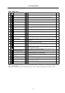
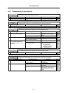
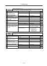
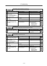
Alarm No.
21
Machine side detector, No signal 2
The pulse-type linear scale or ball screw end detector's ABZ-phase no signal was detected with the
servo, or the encoder no-signal was detected with the spindle.
Investigation details Investigation results Remedies SV SP
The value is not set correctly. Correctly set SV025. 1 Check the servo parameter (SV025.
pen) setting value.
Are the pulse-type detector
parameters set for a serial
communication type detector?
The value is set correctly. Investigate item 3.
{
Encoder orientation is not used. Set SP037/bit0 to 0. 2 Check the spindle parameter
(SP037/bit0) settings.
Encoder orientation is used. Investigate item 3.
{
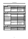
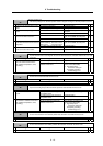
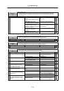
The connector is disconnected (or
loose).
Correctly install. 3 Check whether the drive unit
connectors (servo: CN3, spindle:
CN6) or detector connectors are
disconnected.
The connector is not disconnected. Investigate item 4.
{ {
There is a connection fault. Replace the detector cable. 4 Turn the power OFF, and check the
detector cable connection with a
tester.
The connection is normal. Investigate item 5.
{ {
The alarm is on the drive unit side. Replace the drive unit. 5 Connect to another normal axis drive
unit, and check whether the fault is
on the drive unit side or detector side.
The alarm is on the detector side. Investigate item 6.
{ {
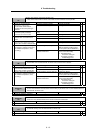
No abnormality is found in particular. Replace the detector.
(With the absolute position system,
the zero point must be established.)
6 Check if there is any abnormality in
the detector's ambient environment.
(Ex. Ambient temperature, noise,
grounding)
An abnormality was found in the
ambient environment.
Take remedies according to the
causes of the abnormality.
Ex. High temperature:
Check the cooling fan.
Incomplete grounding:
Additionally ground.
{ {
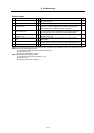
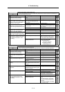
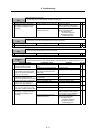
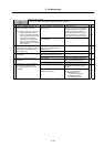
Alarm No.
23
Excessive speed deflection 1
A difference of 50r/min or more between the speed command and speed feedback continued for longer
than the set time.
Investigation details Investigation results Remedies SV SP
The wires are not correctly
connected.
Correctly connect. 1 Check the U, V and W wiring
between the spindle drive unit and
spindle motor.
The wires are correctly connected. Investigate item 2.
{
The correct values are not set. Correctly set. 2 Check the settings for SP034,
SP040, SP055, and SP257 to
SP384.
The correct values are set. Investigate item 3.
{
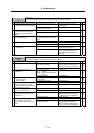
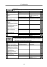
12 seconds or more. Increase the SP055 setting value. 3 Measure the acceleration/
deceleration time constants.
Measure the time required to reach
the reverse run maximum speed from
the forward run maximum speed.
Less than 12 seconds. Investigate item 4.
{
120% or more. Reduce the load. 4 Measure the load during cutting.
Less than 120%. Investigate item 5.
{
There is a problem. Adjust the PLG output waveform. 5 Check the PLG output waveform.
Normal. Replace the drive unit.
{