


3. Setup
3 - 33
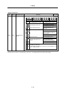
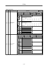
High-gain specifications
No. Abbrev. Parameter name Explanation
S
etting rang
e
(Unit)
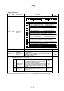
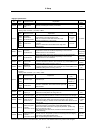
SV039 LMCD
Lost motion
compensation
timing
Set this when the lost motion compensation type2 timing doest not match.
Adjust by increasing the value by 10 at a time.
0 to 2000
(ms)
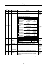
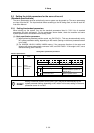
For SV040, the hex. value’s higher order 8bits and lower order 8bits are used for different functions.
"Setting value of SV040" = (Icy×256) + LMCT
Abbrev. Parameter name Explanation
Setting range
(Unit)
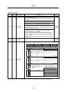
LMCT
(Low
order)
Lost motion
compensation
non-sensitive band
Set the non-sensitive band of the lost motion
compensation in the feed forward control.
When "0" is set, the actual value that is set is 2µm.
Adjust by increasing by 1µm at a time.
0 to 100
(µm)
Icy
(High
order)
Current bias 2
Normally, set to "40" if you use HC202 to HC902, HC203
to HC703.
Use this in combination with SV030 and the high order
8bits of SV045.
0 to 127
SV040
0 to 32767
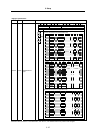
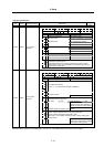
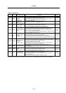
SV041 LMC2
Lost motion
compensation 2
Set this with SV016 (LMC1) only when you wish to set the lost motion
compensation amount to be different depending on the command
directions. Set to "0" as a standard.
-1 to 200
(Stall [rated]
current %)
SV042 OVS2
Overshooting
compensation 2
Set this with SV031 (OVS1) only when you wish to set the overshooting
compensation amount to be different depending on the command
directions. Set to "0" as a standard.
-1 to 100
(Stall [rated]
current %)
SV043 OBS1
Disturbance
observer filter
frequency
Set the disturbance observer filter band. Set to "100" as a standard.
To use the disturbance observer, also set SV037 (JL), SV044 (OBS2) and
SV082/bit7 (obshj). When not using, set to "0".
0 to 1000
(rad/s)
SV044 OBS2
Disturbance
observer gain
Set the disturbance observer gain. The standard setting is "100" to "300".
To use the disturbance observer, also set SV037 (JL), SV043 (OBS1) and
SV082/bit7 (obshj). When not using, set to "0".
0 to 500
(%)
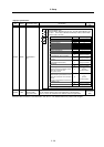
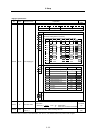
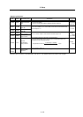
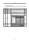
For SV045, the hexadecimal value's higher order 8 bits and lower order 8 bits are used for different
functions.
"Setting value of SV045" = (Icy × 256) + LMCT
Abbrev. Parameter name Explanation
Setting range
(Unit)
TRUB
(Low
order)
Frictional torque
When you use the collision detection function, set the
frictional torque.
0 to 100
(Stall [rated]
current %)
Ib1
(High
order)
Current bias 3
Normally set to "0".
Use this in combination with SV030 and the high order
8bits of SV040.
0 to 127
SV045
0 to 32767
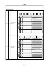
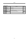
SV046 FHz2
Notch filter
frequency 2
Set the vibration frequency to suppress if machine vibration occurs.
(Valid at 36 or more) When not using, set to "0".
0 to 9000
(Hz)
SV047 EC
Inductive voltage
compensation gain
Set the inductive voltage compensation gain. Set to "100" as a standard.
If the current FB peak exceeds the current command peak, lower the gain.
0 to 200
(%)
SV048 EMGrt
Vertical axis drop
prevention time
Input a length of time to prevent the vertical axis from dropping by delaying
Ready OFF until the brake works when the emergency stop occurs.
Increase the setting by 100msec at a time and set the value where the axis
does not drop.
0 to 20000
(ms)
SV049 PGN1sp
Position loop gain 1
in spindle
synchronous control
Set the position loop gain during the spindle synchronous control
(synchronous tapping, synchronous control with spindle/C axis).
Set the same value as the value of the spindle parameter, position loop
gain in synchronous control.
When performing the SHG control, set this with SV050 (PGN2sp) and
SV058 (SHGCsp).
1 to 200
(rad/s)
SV050 PGN2sp
Position loop gain 2
in spindle
synchronous control
Set this with SV049 (PGN1sp) and SV058 (SHGCsp) if you wish to perform
the SHG control in the spindle synchronous control (synchronous tapping,
synchronous control with spindle/C axis).
When not performing the SHG control, set to "0".
0 to 999
(rad/s)
Parameters with an asterisk * in the abbreviation, such as PC1*, are validated with the NC power turned ON again.