


2. Wiring and Connection
2 - 4
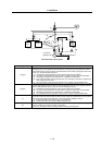
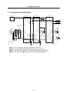
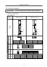
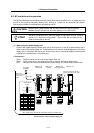
2-2 Main circuit terminal block/control circuit connector
2-2-1 Names and applications of main circuit terminal block signals and control circuit
connectors
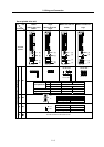
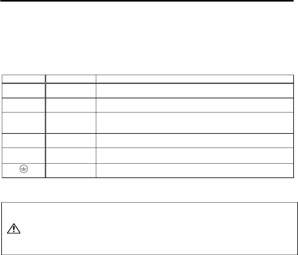
The following table shows the details for each terminal block signal.
Name Signal name Description
L1
.
L2
.
L3
Main circuit power
supply
Main circuit power supply input terminal
Connect a 3-phase 200VAC/200 to 230VAC, 50/60Hz power supply.
L11
L21
Control circuit power
supply
Control circuit power supply input terminal
Connect a single-phase 200VAC/200 to 230VAC, 50/60Hz power supply.
MC1
Contactor control
Contactor control terminal
The MC1 terminal has the same phase as L21. Connect to a different phase than the
phase connected to L21.
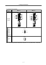
U
.
V
.
W
Motor output
(Single-axis unit)
Servo/spindle motor power output terminal
The servo/spindle motor power terminal (U, V, W) is connected.
LU
.
LV
.
LW
MU
.
MV
.
MW
Motor output
(Dual-axis unit)
Servo motor power output terminal (L-axis/M-axis)
The servo/spindle motor power terminal (U, V, W) is connected.
Protective grounding
(PE)
Grounding terminal
The servomotor/spindle motor grounding terminal is connected and grounded.
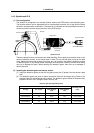
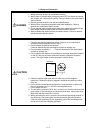
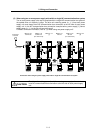
1. Always use one AC reactor per power supply unit. Failure to observe this
could lead to unit damage.
2. When sharing a breaker for several power supply units, of a short-circuit
fault occurs in a small capacity unit, the breaker could trip. This can be
hazardous, so do not share the breaker.
CAUTION
3. Be sure to use the breaker of proper capacity for each power supply unit.