


2. Wiring and Connection
2 - 35
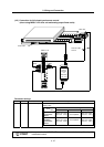
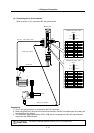
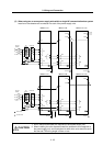
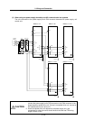
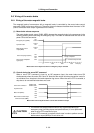
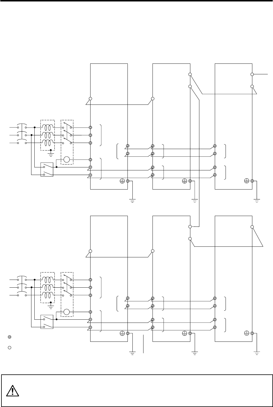
(2) When using two or more power supply units within a single NC communication bus system
Install a no-fuse breaker and a contactor for each of the power supply units.
MC1
T
S
R
Contactor
No-fuse
breake
r
Ground
CN1A
CN4
L1
L2
L3
L11
TE3
TE1
CN1B
L+
L-
MDS-C1-SPMDS-C1-CV
CN4
TE3
TE2
L+
L-
L11
L21
TE2
AC
reactor
Ground
Ground
L21
CN1A
CN1B
MDS-C1-V1/V2
TE3
TE2
L+
L-
L11
L21
Ground
To NC
MC
Breaker
MC1
T
S
R
Contactor
No-fuse
breake
r
Ground
: Main circuit
: Control circuit
CN1A
CN4
L1
L2
L3
L11
TE3
TE1
CN1B
L+
L-
MDS-C1-SPMDS-C1-CV
CN4
TE3
TE2
L+
L-
L11
L21
TE2
AC
reactor
Ground
Ground
L21
CN1A
MDS-C1-V1/V2
TE3
TE2
L+
L-
L11
L21
Ground
MC
Breaker
CAUTION
1. An AC reactor and breaker are required for each power supply unit.
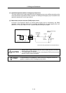
2. When installing the units dispersed install the spindle drive unit adjacent to
the power supply unit, and connections for other drive units should be such
that the total TE2 wiring length is 50cm or less.