


3. Setup
3 - 2
3-1 Initial setup
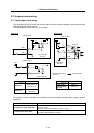
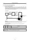
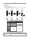
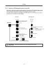
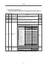
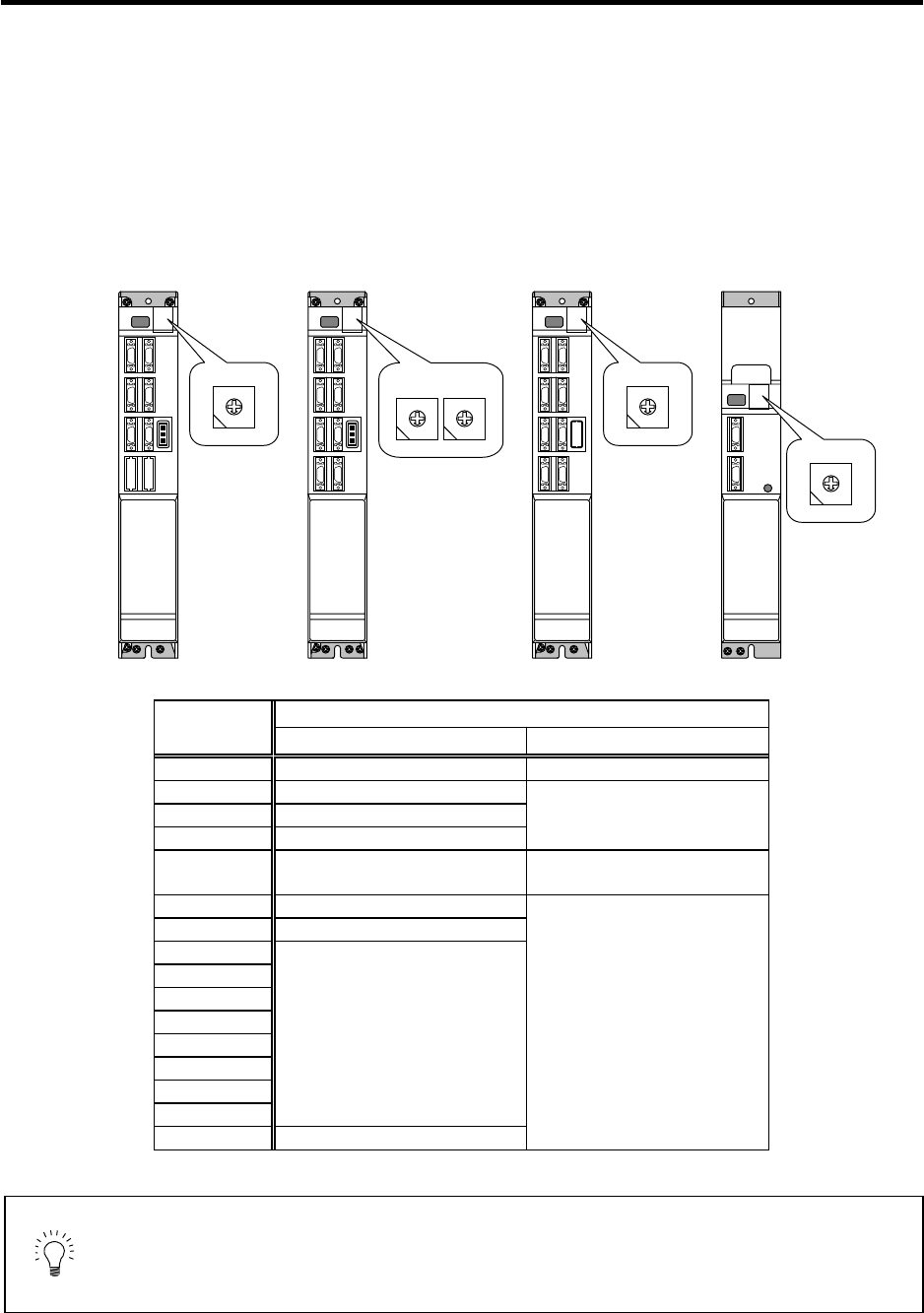
3-1-1 Setting the rotary switch
Before turning on the power, the axis No. must be set with the rotary switch. The rotary switch settings
will be validated when the units are turned ON.
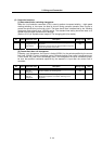
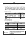
Details
Setting the
rotary switch
Setting the MDS-C1-V1/V2/SP Setting the MDS-C1-CV
0 1st axis External emergency stop invalid
1 2nd axis
2 3rd axis
3 4th axis
Setting prohibited
4 5th axis
External emergency stop valid
(Used CN23)
5 6th axis
6 7th axis
7
8
9
A
B
C
D
E
Setting prohibited
F Axis not used
Setting prohibited
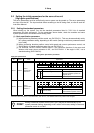
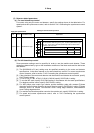
POINT
When an axis that is not used is selected, that axis will not be controlled when
the power is turned ON, and "Ab" will remain displayed on the LED. If the power
of the axis not in use is disconnected, the NC system's emergency stop cannot
be released.
1st axis
Servo drive unit
(MDS-C1-V1)
2nd axis
Servo drive unit
(MDS-C1-V2)
Spindle drive unit
(MDS-C1-SP)
Power supply unit
(MDS-C1-CV)
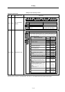
0
1 F
2 E
4 C
3 D
5 B
6 A
7 9
8
0
1 F
2 E
4 C
3 D
5 B
6 A
7 9
8
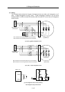
L axis
0
1 F
2 E
4 C
3 D
5 B
6 A
7 9
8
M axis
0
1 F
2 E
4 C
3 D
5 B
6 A
7 9
8
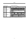
0
1 F
2 E
4 C
3 D
5 B
6 A
7 9
8