


5. Spindle Adjustment
5 - 36
5-3-3 Adjusting the orientation control
(1) Confirming the default parameters
Set the default parameters for each detector used in orientation control.
(a) Motor PLG
Motor PLG orientation is possible only when the spindle and motor are coupled, or when they
are coupled 1:1 with gears (timing belt). The SP025 (GRA1) to SP032 (GRB4) parameters can
be set only to 1. The PLG with Z-phase must be mounted on the motor to be used.
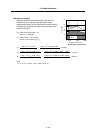
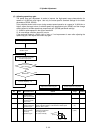
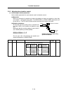
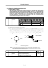
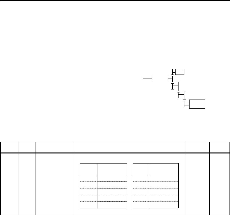
(b) Spindle end detector
An accurate gear ratio (pulley ratio) is required from
the motor shaft to the spindle end detector rotary
axis.
Make sure that the correct number of gear teeth is
set in SP025 (GRA1) to SP032 (GRB4).
SP025 to SP028=A × C × E
SP029 to SP032=B × D × F
Set the gear ratio (A:X) between the spindle and
spindle end detector in SP096 (EGAR).
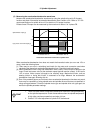
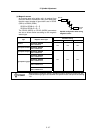
No. Abbr. Parameter name Details
Setting
range
Standard
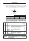
Set the gear ratio between the spindle end and the detector end
(except for the motor PLG) as indicated below.
Setting
value
Gear ratio
(deceleration)
Setting
value
Gear ratio
(acceleration)
0 1 : 1 -1 1 : 2
1 1 : 1/2 -2 1 : 4
2 1 : 1/4 -3 1 : 3
3 1 : 1/8
4 1 : 1/16
SP096 EGAR* Encoder gear ratio -3 to 4 0
S
p
indle end detecto
r
XS
p
indle
Spindle
moto
r
A
BC
D E
F
Spindle configuration when using
spindle end detector