


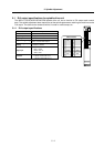
5. Spindle Adjustment
5 - 6
5-2 Spindle control signal
The sequence input/output signals exchanged between the NC and spindle drive unit are explained in
this section. The status of each signal is displayed on the NC SPINDLE MONITOR screen.
5-2-1 Spindle control input (NC to SP)
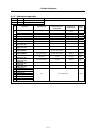
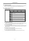
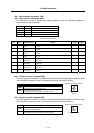
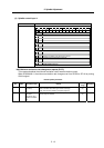
(1) Spindle control input 1
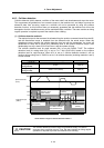
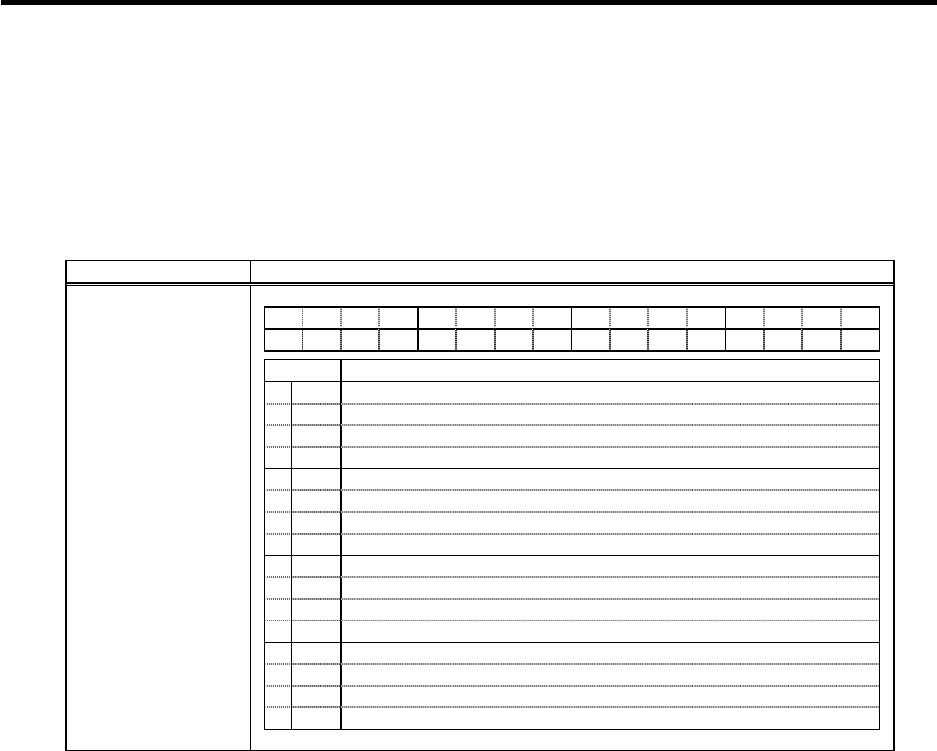
Name Details
F E D C B A 9 8 7 6 5 4 3 2 1 0
G1 MAC TL3 TL2 TL1
ALMR
PRM SRV RDY
bit Details
0
RDY
READY ON command
1
SRV
Servo ON command
2
3
4
5
6
PRM
Parameter conversion command
7
ALMR
Drive unit alarm reset command
8
TL1
Torque limit 1
9
TL2
Torque limit 2
A
TL3
Torque limit 3
B
MAC
Pole position detection check command (only for MDS-C1-SPM)
C
D
E
F
G1
Cutting
Spindle control input 1
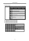
bit0. READY ON command (RDY)
This signal is input when preparations to rotate the motor are completed. The forward run and
reverse run commands will not be accepted even if input before this signal turns ON.
bit1. Servo ON command (SRV)
This is input for position control, excluding orientation. If this signal is not ON, position control will
not be executed even if the spindle control mode selection command's combination indicates the
position control mode.
bit6. Parameter conversion command (PRM)
This is started when the spindle parameters are converted on the NC screen.
bit7. Drive unit alarm reset command (ALMR)
This turns ON while NC reset is input. Spindle alarms that can be reset with NR are reset.