


6. Troubleshooting
6 - 23
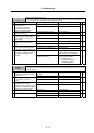
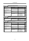
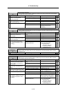
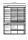
Alarm No.
3F
Speed excessive deflection 2
During constant speed operation, the difference between the speed command and speed feedback
exceeded the set amount and set time.
Investigation details Investigation results Remedies SV SP
The cutting load is large. Lower the cutting load. 1 Check the load value with the spindle
monitor, and investigate the
machine's load state.
The cutting load is not large. Investigate item 2.
{
Locked with a mechanical lock. Remove the cause of the lock. 2 Check whether the spindle rotary
section is locked with a mechanical
lock (C-axis clamp, etc.).
Not locked with a mechanical lock. Investigate item 3.
{
Improved. Replace the drive unit. 3 Try replacing the drive unit.
Not improved. Investigate the motor.
(Check the motor type and
parameters.)
{
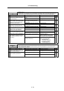
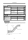
Alarm No.
40
Detector changeover unit, changeover error
During 1-drive unit 2-motor control, an error was detected in the motor changeover signal received form
the detector changeover unit.
Investigation details Investigation results Remedies SV SP
The connector is disconnected (or
loose).
Correctly install. 1 Wiggle the FR-TK unit connector by
hand to check whether it is
disconnected.
The connector is not disconnected. Investigate item 2.
{
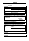
The cable is broken. Replace the cable. 2 Check whether the cable connected
between the spindle drive unit and
FR-TK unit is broken.
The cable is not broken. Investigate item 3.
{
No abnormality is found in particular. Replace the drive unit. 3 Check if there is any abnormality in
the unit's ambient environment.
(Ex. Ambient temperature, noise,
grounding)
An abnormality was found in the
ambient environment.
Take remedies according to the
causes of the abnormality.
Ex. High temperature:
Check the cooling fan.
Incomplete grounding:
Additionally ground.
{
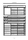
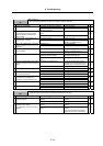
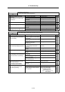
Alarm No.
41
Detector changeover unit, communication error
During 1-drive unit 2-motor control, an error was detected in the communication with the detector
changeover unit.
Investigation details Investigation results Remedies SV SP
1 Check the alarm No. "40" items.
{
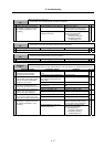
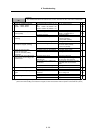
Alarm No.
42
Feedback error 1
With the servo, pulse-type position detector feedback signal error was detected. With the spindle, a
PLG feedback signal error was detected.
Investigation details Investigation results Remedies SV SP
The connector is disconnected (or
loose).
Correctly install. 1 Check whether the drive unit
connectors (servo: CN3, spindle:
CN6) or detector connectors are
disconnected.
The connector is not disconnected. Investigate item 2.
{ {
There is a connection fault. Replace the detector cable. 2 Turn the power OFF, and check the
detector cable connection with a
tester.
The connection is normal. Investigate item 3.
{ {
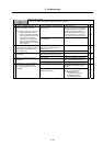
The alarm is on the drive unit side. Replace the drive unit. 3 Connect to another normal axis drive
unit, and check whether the fault is
on the drive unit side or detector side.
The alarm is on the detector side. Servo : Investigate item 5.
Spindle : Investigate item 4.
{ {
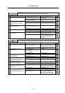
There is a problem. Adjust the PLG output waveform. 4 Check the PLG output waveform.
Normal Investigate item 5.
{
No abnormality is found in particular. Replace the detector.
(With the absolute position system,
the zero point must be established.)
5 Check if there is any abnormality in
the detector's ambient environment.
(Ex. Ambient temperature, noise,
grounding)
An abnormality was found in the
ambient environment.
Take remedies according to the
causes of the abnormality.
Ex. High temperature:
Check the cooling fan.
Incomplete grounding:
Additionally ground.
{ {