


3. Setup
3 - 43
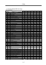
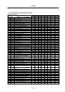
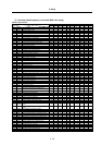
(4) Setting the power supply type
Set the drive unit connected to the power supply unit with the CN4 connector. This does not need
to be set if the power supply for the axis is not connected with the CN4 connector. (Set "0000".)
If the power supply unit is connected with the spindle drive unit, the parameters do not need to be
set on the servo side. When connected to a 2-axis servo drive unit (MDS-C1-V2), set the power
supply type for one of the two target axes.
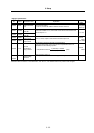
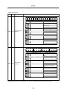
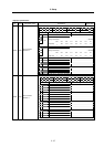
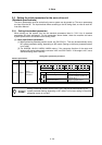
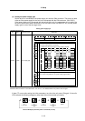
Setting power supply type
Standard specifications
No. Abbrev. Parameter name Explanation
F E D C B A 9 8 7 6 5 4 3 2 1 0
amp rtyp ptyp
bit Explanation
0
1
When the CN4 connector of the drive unit and the power supply are
connected, setting below is necessary.
2 To validate the external emergency stop function, add 40h.
3 Setting 0x 1x 2x 3x 4x 5x 6x 7x 8x
4
ptyp
x0
Not
used
CV-300
5 x1 CV-110 CR-10
6 x2 CV-220 CR-15
7 x3 CR-22
x4
C
V-3
7
CR-37
x5 CV-150
MDS-B-
CVE-450
MDS-B-
CVE-550
x6
C
V-5
5
CV-260 CR-55
x7 CV-370
x8
C
V-7
5
CR-75
x9 CV-185 CR-90
8 Set the regenerative resistor type when MDS-A-CR is used.
9 Set "0" when using MDS-C1-CV (power supply regeneration).
A
B
rtyp
C Always set "0".
D
E
amp
F
SV036 PTYP*
Power supply type
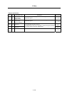
Parameters with an asterisk * in the abbreviation, such as PC1*, are validated with the NC power turned ON again.
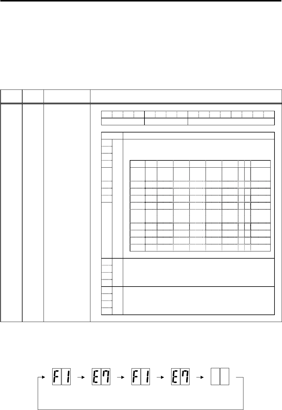
If alarm 7F occurs after setting the initial parameters, turn the drive unit power ON again. If the unit's
LEDs indicate the following emergency stop state, the unit has started up normally.
Normal LED display when NC power is turned ON (1st axis)
F1
F+axis No.
E7
Emergency
sto
p
Not lit
F1
F+axis No.
E7
Emergency
sto
p