


6. Troubleshooting
6 - 6
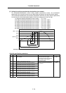
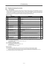
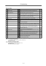
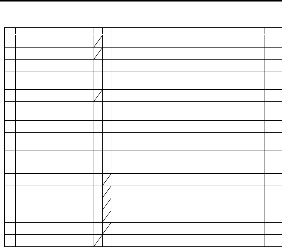
Drive unit alarm
No. Alarm name SV SP Alarm details Reset
40 Detector changeover unit,
changeover error
§
During 1-drive unit 2-motor control, an error was detected in the motor
changeover signal received form the detector changeover unit.
PR
41 Detector changeover unit,
communication error
§
During 1-drive unit 2-motor control, an error was detected in the
communication with the detector changeover unit.
PR
42 Feedback error 1
§ §
With the servo, pulse-type position detector feedback signal error was
detected. With the spindle, a PLG feedback signal error was detected.
PR
43 Feedback error 2
§ §
With the servo, an excessive error was detected in the position data for
the motor side detector and machine side detector. With the spindle, an
error was detected in the encoder feedback signal.
PR
44 C-axis changeover alarm
§
When using the coil changeover control motor, the mode was changed
to C-axis control while the high-speed coil was selected.
NR
46 Motor overheat
{ {
The temperature protection function in the motor or detector activated. NR
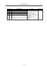
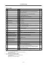
4E NC command mode error
§
A spindle control mode selection exceeding the specifications was
input.
NR
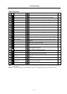
50 Overload 1
{
§
The overload detection level reached 100% or more. The motor or drive
unit is in the overload state.
NR
51 Overload 2
§ §
With the servo, a current command exceeding 95% of the unit's
maximum current continued for one second or more. With the spindle, a
load exceeding the continuous rating continued for 30 minutes or more.
NR
52 Excessive error 1
{ {
With the servo, the difference of the motor's actual position at servo ON
and the theoretical position exceeded the setting value. With the
spindle, the difference of the position command and position feedback
exceeded the setting value.
NR
53 Excessive error 2
§
The difference of the motor's actual position at servo OFF and the
theoretical position exceeded the setting value.
NR
54 Excessive error 3
{
The motor current was not detected when the excessive error 1 alarm
occurred.
NR
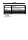
58 Collision detection 1 G0
{
When the collision detection function is valid, the disturbance torque
exceeded the collision detection value during rapid traverse (G0).
NR
59 Collision detection 1 G1
{
When the collision detection function is valid, the disturbance torque
exceeded the collision detection level during cutting feed (G1).
NR
5A Collision detection 2
{
When the collision detection function is valid, the command torque
reached the motor's maximum torque.
NR
5C Orientation feedback error
§
After orientation was completed, the command and feedback error
exceeded the parameter setting.
PR
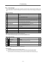
(Note 1) Motor stopping method applied when self-axis drive unit alarm occurs is indicated in SV for servo and in SP for spindle.
(Note 2) Servo (SV) alarm stopping method
{: Deceleration control (when SV048, SV055 or SV056 is set)
§: Dynamic brake stop
: Initial error (while motor is stopped)
(Note 3) Spindle (SP) alarm stopping method
{: Deceleration control (when SP038/bit0=1 is set)
§: Coast to a stop
: Initial error (while motor is stopped)