


1. Installation
1 - 4
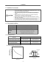
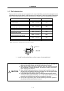
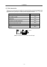
1-1-5 Shaft characteristics
There is a limit to the load that can be applied on the motor shaft. Make sure that the load applied on the
radial direction and thrust direction, when mounted on the machine, is below the tolerable values given
below. These loads may affect the motor output torque, so consider them when designing the machine.
Servomotor Tolerable radial load Tolerable thrust load
HA053NS, HA13NS 78.4N (L=26mm) 49N
HA23NS, HA33NS
HA23NT, HA33NT
245N (L=30 mm) 147N
HC103RT, HC153RT, HC203RT 392N (L=45 mm) 196N
HC52T, HC102T, HC152T
HC53T, HC103T, HC153T
392N (L=58 mm) 490N
HC103RS, HC153RS, HC203RS 686N (L=45 mm) 196N
HC353RS, HC503RS 980N (L=63 mm) 392N
HC52S, HC102S, HC152S
HC53S, HC103S, HC153S
980N (L=55 mm) 490N
HC202S, HC352S, HC452S, HC702S
HC203S, HC353S, HC453S, HC703S
2058N (L=79 mm) 980N
HC902S
HA-LF11K2-S8
2450N (L=85 mm) 980N
HA-LF15K2-S8 2940N (L=100 mm) 980N
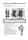
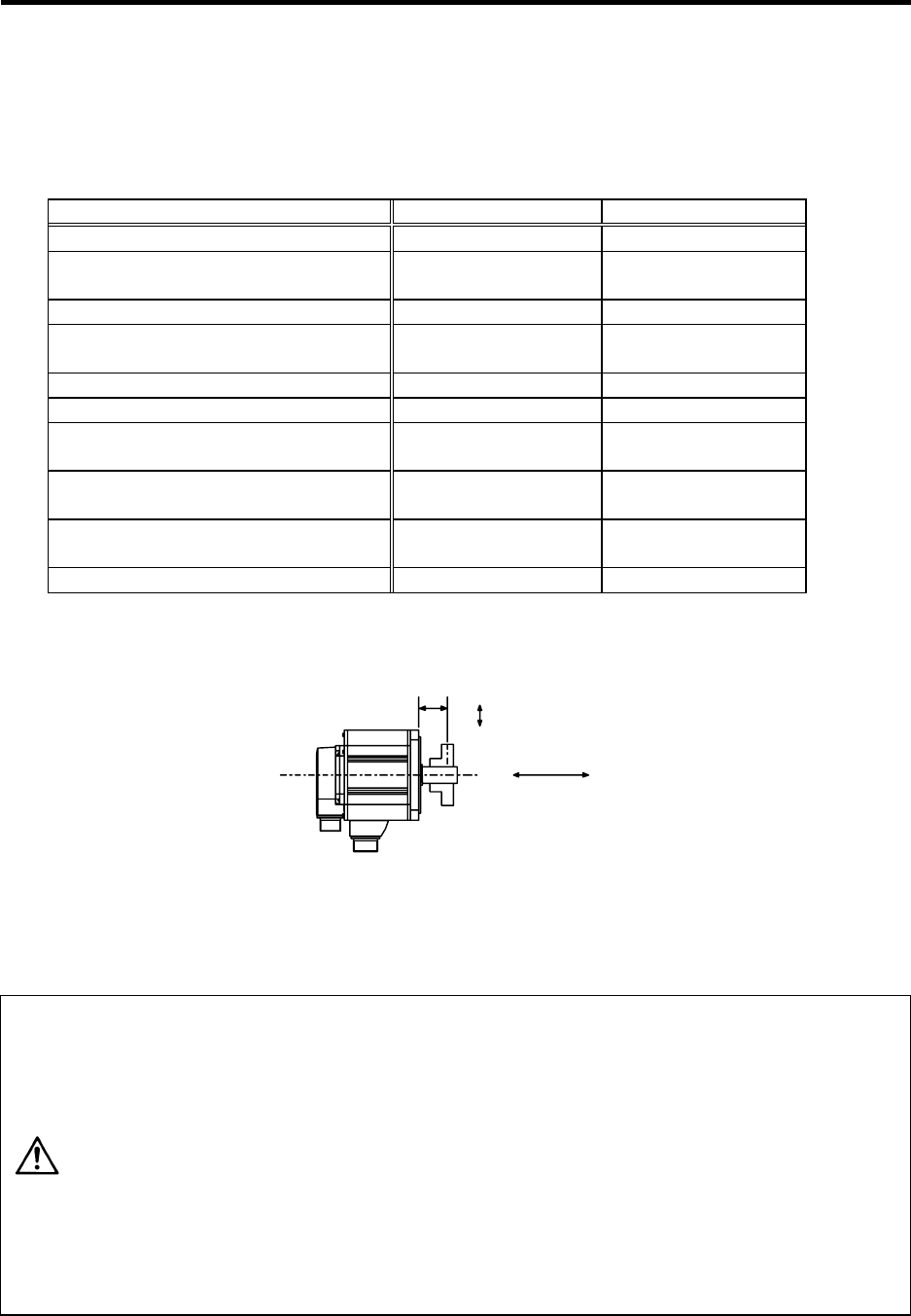
Note: The symbol L in the table refers to the value of L below.
Thrust load
Radial load
L
L : Length from flange installation surface to center of load weight [mm]
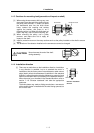
CAUTION
1. Use a flexible coupling when connecting with a ball screw, etc., and keep the
shaft core deviation to below the tolerable radial load of the shaft.
2. When directly installing the gear on the motor shaft, the radial load increases
as the diameter of the gear decreases. This should be carefully considered
when designing the machine.
3. When directly installing the pulley on the motor shaft, carefully consider so
that the radial load (double the tension) generated from the timing belt tension
is less than the values shown in the table above.
4. In machines where thrust loads such as a worm gear are applied, carefully
consider providing separate bearings, etc., on the machine side so that loads
exceeding the tolerable thrust loads are not applied to the motor.
5. Do not use a rigid coupling as an excessive bending load will be applied on
the shaft and could cause the shaft to break.