


6. Troubleshooting
6 - 40
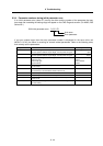
6-3-3 Troubleshooting for each warning No.
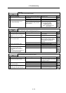
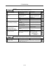
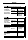
Warning No.
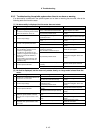
90
Detector, initial communication error
Initial communication with the absolute position linear scale was not possible.
Investigation details Investigation results Remedies SV SP
The setting is incorrect. Correctly set SV025. 1 Check the servo parameter
(SV025.pen) setting.
The setting is correct. Investigate item 2.
{
The connector is disconnected
(loose).
Correctly install. 2 Check whether the drive unit
connector (CN3) and detector
connector are disconnected.
The connector is not disconnected. Investigate item 3.
{
The connection is faulty. Replace the detector cable (CN3
side).
3 Turn the power OFF, and check the
detector cable connection with a
tester.
The connection is normal. Investigate item 4.
{
No abnormality is found in particular. Replace the tool end detector.
(With the absolute position system,
the zero point must be established.)
4 Check if there is any abnormality in
the tool end detector's ambient
environment.
(Ex.: Ambient temperature, noise,
grounding)
An abnormality was found in the
ambient environment.
Take remedies according to the
causes of the abnormality.
Ex. High temperature:
Check the cooling fan.
Incomplete grounding:
Additionally ground.
{
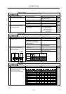
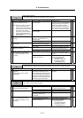
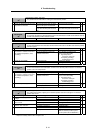
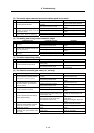
Warning No.
91
Detector, communication error
An error was detected in the communication with the detector for the absolute position detection
system.
Investigation details Investigation results Remedies SV SP
The connector is disconnected (or
loose).
Correctly install. 1 Check whether the drive unit
connectors (CN3) or detector
connectors are disconnected.
The connector is not disconnected. Investigate item 2.
{
The cables are wired near each
other. (Noise is entering from the
power cable.)
Improve the cable wiring. 2 Is the detector cable wired in the
same conduit as the motor's power
cable or are the two cables laid in
parallel near each other?
The wires are sufficiently separated. Investigate item 3.
{
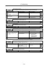
The motor FG wire is grounded on
the motor side.
Ground the motor to one point,
connecting the wires together on the
drive unit side.
3 Is the motor FG wire connected only
to the drive unit which drives it?
(Is the motor grounded to one point?)
The motor is grounded to one point. Investigate item 4.
{
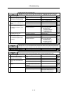
There is a connection fault. Replace the detector cable. 4 Turn the power OFF, and check the
detector cable connection with a
tester. (Is the cable shielded?)
The connection is normal. Investigate item 5.
{
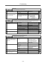
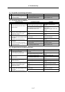
The alarm is on the drive unit side. Replace the drive unit. 5 Connect to another normal axis drive
unit, and check whether the fault is
on the drive unit side or detector side.
The alarm is on the detector side. Investigate item 6.
{
No abnormality is found in particular. Replace the detector.
(With the absolute position system,
the zero point must be established.)
6 Check if there is any abnormality in
the detector's ambient environment.
(Ex. Ambient temperature, noise,
grounding)
An abnormality was found in the
ambient environment.
Take remedies according to the
causes of the abnormality.
Ex. High temperature:
Check the cooling fan.
Incomplete grounding:
Additionally ground.
{
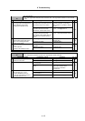
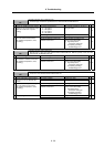
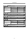
Warning No.
92
Detector, protocol error
An error was detected in the data for the absolute position detection system.
Investigation details Investigation results Remedies SV SP
No abnormality is found in particular. Investigate item 2. 1 Check if there is any abnormality in
the detector's ambient environment.
(Ex. Ambient temperature, noise,
grounding)
An abnormality was found in the
ambient environment.
Take remedies according to the
causes of the abnormality.
Ex. High temperature:
Check the cooling fan.
Incomplete grounding:
Additionally ground.
{
Occurs frequently. Replace the detector. 2 Check the repeatability.
Is not repeated. Investigate item 1.
{ {