


4. Servo Adjustment
4 - 25
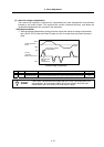
(3) Adjusting the lost motion compensation timing
If the speed loop gain has been lowered from the standard setting value because the machine
rigidity is low or because machine resonance occurs easily, or when cutting at high speeds, the
quadrant protrusion may appear later than the quadrant changeover point on the servo control. In
this case, suppress the quadrant protrusion by setting the lost motion compensation timing
(SV039: LMCD) to delay the LMC compensation.
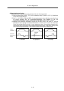
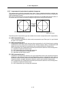
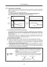
<Adjustment method>
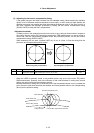
If a delay occurs in the quadrant protrusion in the circle or arc cutting as shown below in respect to
the cutting direction when CNC sampling measurement (DBB measurement) or actual cutting is
carried out, and the compensation appears before the protrusion position, set the lost motion
compensation timing (SV039: LMCD).
While measuring the arc path, increase LMCD by 10 ms at a time, to find the timing that the
protrusion and compensation position match.
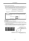
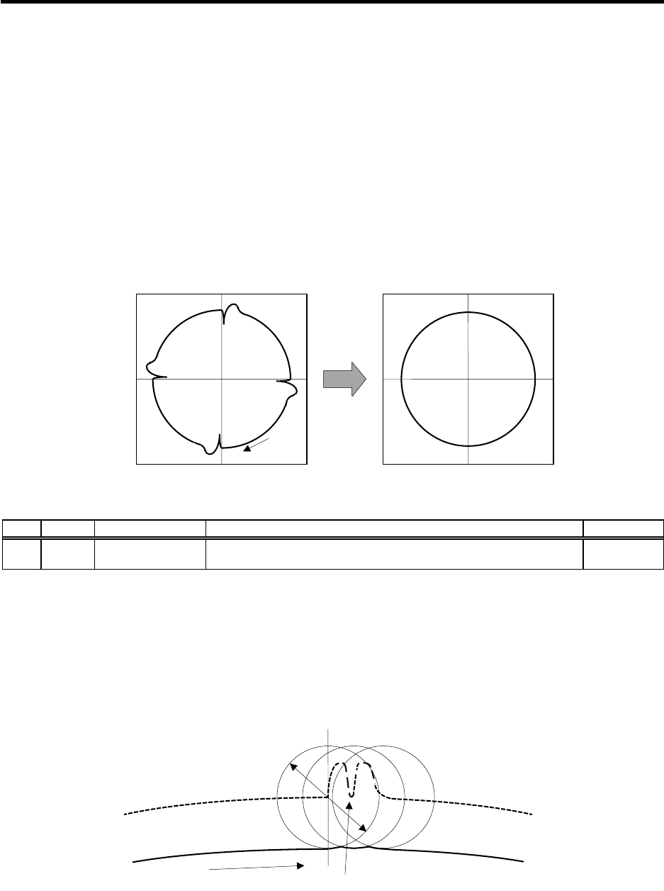
Before timing delay compensation After timing delay compensation
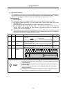
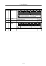
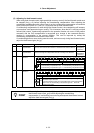
No. Abbrev. Parameter name Explanation Setting range
SV039 LMCD Lost motion
compensation timing
Set this when the lost motion compensation timing does not match. Adjust
while increasing the value by 10 at a time.
0 to 2000
(ms)
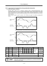
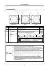
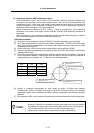
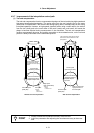
When the LMCD is gradually raised, a two-peaked contour may occur at the motor FB position
DBB measurement. However, due to the influence of the cutter diameter in cutting such as end
milling, the actual cutting surface becomes smooth.
Because satisfactory cutting can be achieved even if this two-peaked contour occurs, consider the
point where the protrusion becomes the smallest and finest possible without over compensating
(bite-in) as the optimum setting.
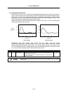
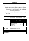
Cutter center path
A
ctual cutting surface
Cutting direction
Quadrant changeover point
Point of LMC compensation execution
Cutter diameter
A
fter
compensation
Cutting
direction