3. Setup
3 - 106
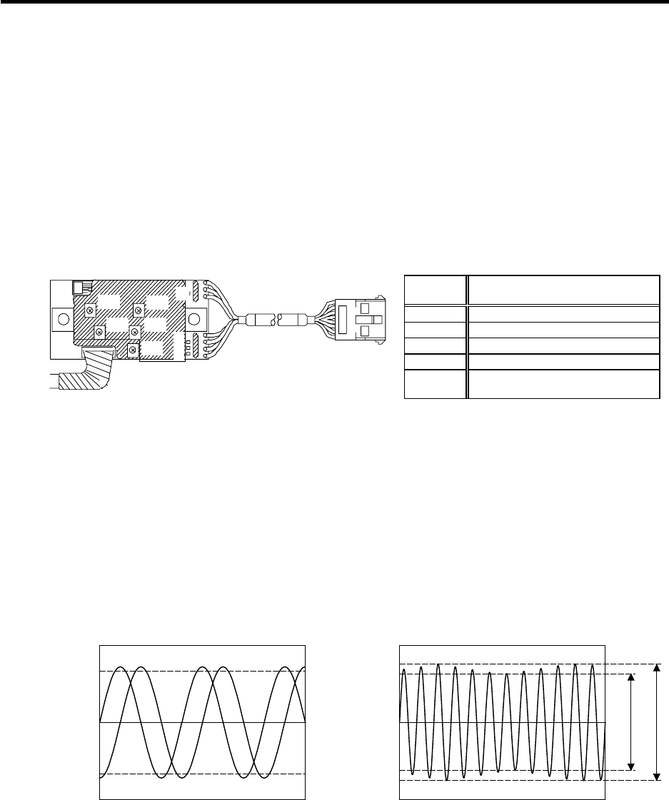
(4) Adjusting the A phase and B phase output signal
[1] Set the drive unit in the open loop operation state. (Set the spindle parameter SP038/bitF to
"1" and turn the NC power ON again.) There are cases when sudden speed changes cannot
be followed during open loop operation, so gradually change the speed command.
[2] Forward run the motor and rotate the PLG at the reference speed.
[3] Using the PCB volume VR1 to VR4, adjust so that the A phase and B phase signals are within
the specified range. If the correct waveform cannot be attained even after adjusting with VR1
to VR4, adjust the gap again.
[4] Reverse run the motor and rotate the PLG at the reference speed.
[5] Adjust the output waveform by adjusting VR1 to VR4 in the same manner.
VR1
VR2
VR4
VR3
VR5
G
B
A
Z
PCB section
[6] Set the drive unit to the closed loop operation state (normal operation).
[7] Run the motor at the maximum speed, and confirm that the A phase and B phase output
voltage peak value is larger than 0.8V on both the plus side and minus side during both
forward run and reverse run.
[8] Run the motor at the reference speed, and confirm that the A phase and B phase output signal
envelope is 0.4V or less.
The envelope is calculated by the expression below.
(Envelope) = (Maximum amplitude α) - (Minimum amplitude β)
[9] If the envelope is larger than the designated value, the deflection of the detection gears' outer
diameter may be large, so check the deflection.
Example of A phase/B phase signal waveform
during forward run at maximum speed
Definition of envelope
Volume function
Check
terminal
Signal name
VR1 A phase offset adjustment
VR2 A phase gain adjustment
VR3 B phase offset adjustment
VR4 B phase gain adjustment
VR5
Z phase pulse width adjustment
(Already adjusted before shipment)
A phase
B
hase
0.8
Voltage [V]
-0.8
0
Time
Voltage [V]
0
Time
Minimum am
litude:
Maximum am
litude: α


