


5. Spindle Adjustment
5 - 15
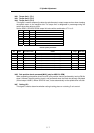
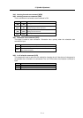
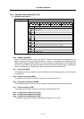
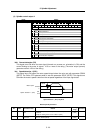
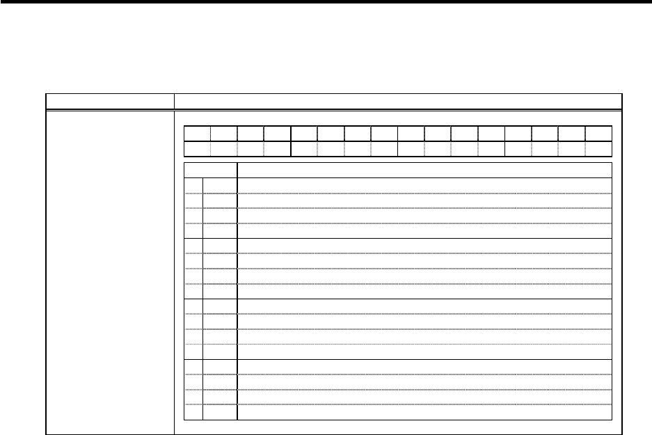
5-2-2 Spindle control output (SP to NC)
(1) Spindle control output 1
Name Details
F E D C B A 9 8 7 6 5 4 3 2 1 0
CL INP ZFIN MAO
TL3A TL2A TL1A
ALM
PRMA
WRN
SON RON
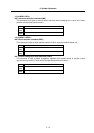
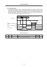
bit Details
0
RON
In READY ON
1
SON
In servo ON
2
3
4
WRN
In drive unit warning
5
6
PRMA
In parameter conversion
7
ALM
In drive unit alarm
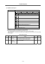
8
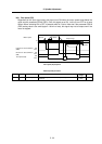
TL1A
In torque limit 1 signal input
9
TL2A
In torque limit 2 signal input
A
TL3A
In torque limit 3 signal input
B
MAO
Magnetic pole position checked (Only for MDS-C1-SPM)
C
D
ZFIN
Z-phase passed
E
INP
In position loop in-position
F
CL
Limiting current
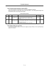
Spindle control output 1
bit0. In READY ON (RON)
When the READY ON signal is input from the NC, if there is no abnormality, this signal turns on in
approx. one second. If the start signal (forward run, reverse run, orientation) is turned ON while this
signal is ON, the motor will start rotating. If an alarm occurs in the spindle drive unit, this signal will
turn OFF. If the READY ON signal from the NC turns OFF while the spindle motor is rotating, the
motor will decelerate to a stop, but this signal will remain ON until the motor stops.
bit1. In servo ON (SON)
This signal turns ON after position control is switched when performing position control except for
the orientation.
bit4. In drive unit warning (WRN)
This signal turns ON when a warning is occurring in the spindle drive unit.
bit6. In parameter conversion (PRMA)
The parameters sent from the NC are converted into effective parameters for spindle control.
bit7. In drive unit alarm (ALM)
This signal turns ON when an alarm is occurring in the spindle drive unit.
bit8. In torque limit 1 signal input (TL1A)
bit9. In torque limit 2 signal input (TL2A)
bitA. In torque limit 3 signal input (TL3A)
The respective signal turns ON when the torque limit signal 1 to 3 is input.