


3. Setup
3 - 109
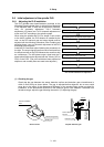
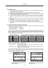
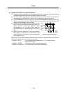
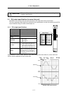
(8) Adjusting the Z phase and A phase difference
[1] Stop the motor, and make sure that the detection gears are not rotating. The sensor could be
damaged if adjustments are carried out while the gears are rotating.
[2] Using a clearance gauge, adjust so that the gap between the sensor direction surface and the
detection gears’ circumference is 0.15±0.01mm, and loosen the sensor fixing screw.
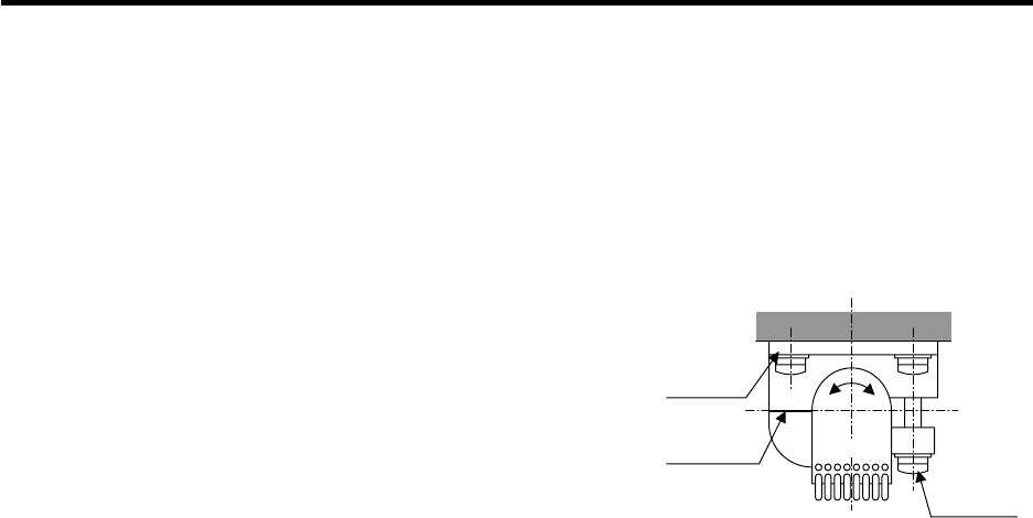
[3] The phase difference of the Z phase to the A phase can be adjusted by rotating the sensor as
shown on the right. At this time, rotate the sensor a little bit while using the marking lines on
the sensor and installation seat as a guide.
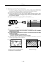
[4] Tighten the sensor fixing screw so that the sensor
does not move, and confirm that the gap between the
sensor detection surface and detection gears'
circumference is 0.15 ± 0.01mm. Then, rotate the
gears and confirm the phase difference as explained
above.
[5] When the phase difference is within the tolerable
range, apply a locking agent on the sensor fixing
screw, and then fix the sensor. Check the gap again
after fixing the sensor.
Always carry out the initial automatic adjustment when starting the spindle system up for the first
time or when the spindle drive unit has been replaced.
[1] MDS-C1-SPM : "3-6-2 Z-phase automatic adjustment" + "3-6-3 Motor end PLG
automatic adjustment"
[2] MDS-C1-SP/SPH : "3-6-3 Motor end PLG automatic adjustment"
[3] MDS-C1-SPX/SPHX : "3-6-4 Spindle end PLG automatic adjustment"
Marking
line
Rotate
Sensor
fixing
screw
Sensor
installation
seat
Adjusting the Z phase difference