


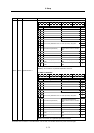
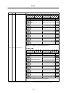

3. Setup
3 - 68
M60S
Series
No.
Abbrev. Parameter name Details
Setting range
(Unit)
3037
3038
3039
3040
taps 21
22
23
24
Synchronous tap
switching spindle
speed 2
Set the spindle rotation speed at which the step-2
acceleration/deceleration time constant is to be switched at gear 00, 01,
10, or 11.
0 to 99999
(r/min)
3041
3042
3043
3044
tapt 21
22
23
24
Synchronous tap
switching time
constant 2
Set the time constant to reach synchronous tap switching spindle
rotation speed 2 (taps 21 to 24) at gear 00, 01, 10, or 11.
1 to 5000 (ms)
3045
3046
3047
3048
tapt 31
32
33
34
Synchronous tap
switching time
constant 3
Set the time constant to reach the maximum rotation speed (smax 1 to 4)
at gear 00, 01, 10, or 11.
1 to 5000 (ms)
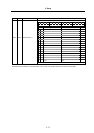
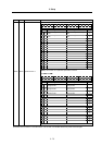
3049 spt
Spindle
synchronization
acceleration/
deceleration time
constant
Set the acceleration/deceleration time constant for when the spindle
synchronization command's rotation speed changes during spindle
synchronous control.
0 to 9999 (ms)
3050 sprlv
Spindle synchro-
nization rotation
speed attainment
level
The spindle rotation speed synchronization complete signal will turn ON
when the difference of the reference spindle and synchronous spindle
actual rotation speeds is less than the level set for the synchronous
spindle rotation speed command value during spindle synchronous
control.
0 to 4095
(pulse)
(1 pulse =
0.088°)
3051 spplv
Spindle phase
synchronization
attainment level
The spindle phase synchronization complete signal will turn ON when
the phase difference of the reference spindle and synchronous spindle is
less than the set level during spindle phase synchronization control.
0 to 4095
(pulse)
(1 pulse =
0.088°)
3052 spplr
Spindle motor
spindle relative
polarity
Set the spindle motor and spindle's relative polarity.
Spindle CW rotation at motor CW rotation: Positive polarity Spindle CCW
rotation at motor CW rotation: Negative polarity
0: Positive
polarity
1: Negative
polarity
3053 sppst
Spindle end
detector
Z -phase position
Set the deviation amount from the spindle's reference position to the
spindle end detector's Z phase.
The deviation amount is obtained using the clockwise direction looking
from the front of the spindle as the positive direction.
0 to 359999
(1/1000°)
3054 sptc1
Spindle synchro-
nization multi-step
acceleration/
deceleration
changeover
speed 1
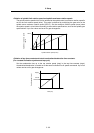
Set the spindle speed for changing the 1st step's
acceleration/deceleration time constant.
0 to 99999
(r/min)
3055 sptc2
Spindle synchro-
nization multi-step
acceleration/
deceleration
changeover
speed 2
Set the spindle speed for changing the 2nd step's
acceleration/deceleration time constant.
0 to 99999
(r/min)
3056 sptc3
Spindle synchro-
nization multi-step
acceleration/
deceleration
changeover
speed 3
Set the spindle speed for changing the 3rd step's
acceleration/deceleration time constant.
0 to 99999
(r/min)
3057 sptc4
Spindle synchro-
nization multi-step
acceleration/
deceleration
changeover
speed 4
Set the spindle speed for changing the 4th step's
acceleration/deceleration time constant.
0 to 99999
(r/min)
3058 sptc5
Spindle synchro-
nization multi-step
acceleration/
deceleration
changeover
speed 5
Set the spindle speed for changing the 5th step's
acceleration/deceleration time constant.
0 to 99999
(r/min)