


6. Troubleshooting
6 - 45
6-3-5 Troubleshooting the spindle system when there is no alarm or warning
If an abnormality is observed in the spindle system but no alarm or warning has occurred, refer to the
following table and check the state.
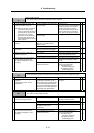
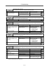
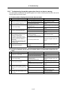
[1] No abnormality is displayed, but the motor does not rotate.
Investigation item Investigation results Remedies
The wiring is incorrect, the screws are
loose, or the cables are disconnected.
Correctly wire. Correctly tighten the
screws. Replace the cables.
1
Check the wiring around the spindle drive
unit.
Also check for loosening in the terminal
screws and disconnec- tions, etc.
No particular problems found.
Investigate investigation item 2 and
remedy.
The voltage is exceeding the
specification value.
Restore the power to the correct state.
2 Check the input voltage.
The voltage is within the specification
value.
Investigate investigation item 3 and
remedy.
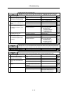
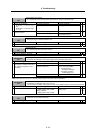
The correct values are not set. Set the correct values.
3 Check all of the spindle parameters.
The correct values are set.
Investigate investigation item 4 and
remedy.
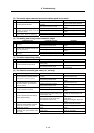
The signals are not input or the
sequence is incorrect.
The orientation command is input.
Correct the input signals.
4
Check the input signals.
• Are the READY, forward run and
reverse run signals input?
• In particular, the forward run and
reverse run signals must be input at
least one second after READY is
turned ON.
• Check whether the forward run and
reverse run signals are turned ON
simultaneously.
No particular problems found.
Investigate investigation item 5 and
remedy.
The speed command is not input
correctly.
Input the correct speed command.
5 Check the speed command.
The speed command is input correctly. Replace the unit.
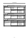
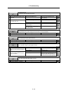
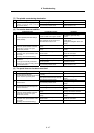
[2] No fault is displayed, but the motor only rotates slowly, or a large noise is heard from the
motor.
Investigation item Investigation results Remedies
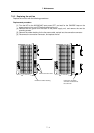
The wires are not connected correctly. Correctly connect.
1
Check the U, V and W wiring between the
spindle drive unit and motor.
The wires are connected correctly.
Investigate investigation item 2 and
remedy.
2 Check the input voltage.
One of the three phases is not within the
specification value.
No particular problems found.
Restore the power to the correct state.
Investigate investigation item 3 and
remedy.
The speed command is not input
correctly.
Check the NC and PLC sequence.
3 Check the speed command.
The speed command is input correctly.
Investigate investigation item 4 and
remedy.
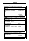
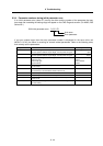
The connector is disconnected (or
loose).
Correctly connect the connector.
4
Tug on the connector by hand to check
whether the speed detector connector
(drive unit side and speed detector side)
is loose.
The connector is not disconnected (or
loose).
Investigate investigation item 5 and
remedy.
The connection is faulty or disconnected.
Replace the detector cable.
Correct the connection.
5
Turn the power OFF, and check the
connection of the speed detector cable
with a tester.
The connection is normal. Replace the drive unit.