


6. Troubleshooting
6 - 14
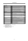
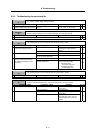
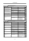
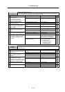
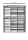
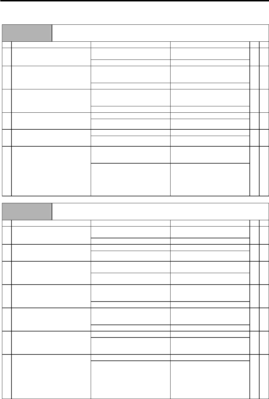
Alarm No.
1F
Machine side detector, communication error
An error was detected in the communication data with the linear scale or ball screw end detector. Or,
the communication was cut off.
Investigation details Investigation results Remedies SV SP
The connector is disconnected (or
loose).
Correctly install. 1 Check whether the drive unit
connectors (CN3) or detector
connectors are disconnected.
The connector is not disconnected. Investigate item 2.
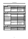
{
The cables are wired near each
other. (Noise is entering from the
power cable.)
Improve the cable wiring. 2 Is the detector cable wired in the
same conduit as the motor's power
cable or are the two cables laid in
parallel near each other?
The wires are sufficiently separated. Investigate item 3.
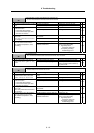
{
The motor FG wire is grounded on
the motor side.
Ground the motor to one point,
connecting the wires together on the
drive unit side.
3 Is the motor FG wire connected only
to the drive unit which drives it?
(Is the motor grounded to one point?)
The motor is grounded to one point. Investigate item 4.
{
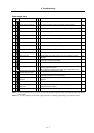
There is a connection fault. Replace the detector cable. 4 Turn the power OFF, and check the
detector cable connection with a
tester. (Is the cable shielded?)
The connection is normal. Investigate item 5.
{
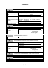
The alarm is on the drive unit side. Replace the drive unit. 5 Connect to another normal axis drive
unit, and check whether the fault is
on the drive unit side or detector side.
The alarm is on the detector side. Investigate item 6.
{
No abnormality is found in particular. Replace the detector.
(With the absolute position system,
the zero point must be established.)
6 Check if there is any abnormality in
the detector's ambient environment.
(Ex. Ambient temperature, noise,
grounding)
An abnormality was found in the
ambient environment.
Take remedies according to the
causes of the abnormality.
Ex. High temperature:
Check the cooling fan.
Incomplete grounding:
Additionally ground.
{
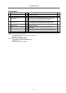
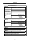
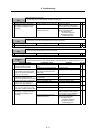
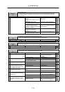
Alarm No.
20
Motor side detector, No signal 1
A PLG Z-phase no signal was detected.
An error was detected in the A/B phase output waveform during PLG automatic adjustment.
Investigation details Investigation results Remedies SV SP
The connector is disconnected (or
loose).
Correctly install. 1 Check whether the drive unit
connectors (CN5) or detector
connectors are disconnected.
The connector is not disconnected. Investigate item 2.
{
There is a connection fault. Replace the detector cable. 2 Turn the power OFF, and check the
detector cable connection with a
tester.
The connection is normal. Investigate item 3.
{
The alarm occurred during PLG
automatic adjustment.
Investigate item 4. 3 Check whether the alarm occurred
during PLG automatic adjustment.
The alarm occurred during normal
operation.
Investigate item 5.
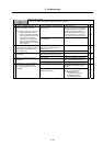
{
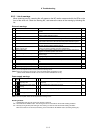
There is a problem. (The A/B phase
input voltage is 0.8V or less or 2.2V
or higher.)
Adjust the PLG output waveform. 4 Check the PLG output waveform (A/B
phase).
Normal Investigate item 6.
{
There is a problem. (The output
waveform is 0V even after the gears'
Z-phase is passed.)
Investigate item 7. 5 Check the PLG output waveform
(Z-phase).
Normal Investigate item 6.
{
Occurs each time. Replace the drive unit. 6 Check the occurrence frequency.
Occurs occasionally. Check whether the cable is
disconnected, whether there is a
contact fault, or a detector fault.
{
No abnormality is found in particular. Replace the PLG detector. 7 Check if there is any abnormality in
the unit's ambient environment.
(Ex. Ambient temperature, noise,
grounding)
An abnormality was found in the
ambient environment.
Take measures according to the error
cause.
Cable disconnection, contact fault.
The sensor is hot during high-load
operation.
Review the operation, and adjust
the Z-phase again.
{