


2. Wiring and Connection
2 - 28
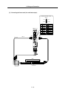
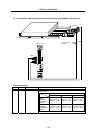
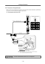
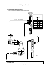
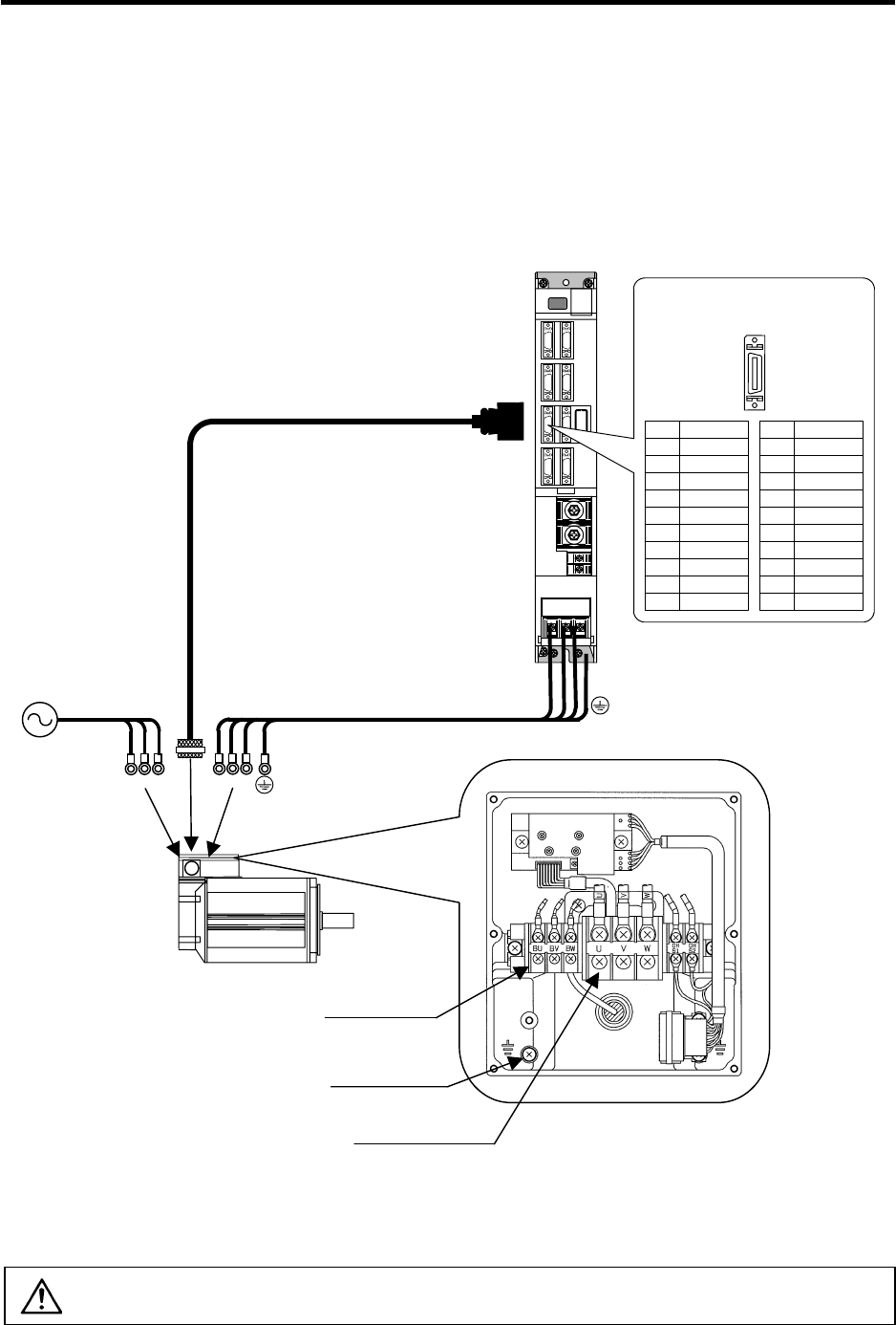
2-4-4 Connection of the spindle motor
Refer to each motor specifications for details on the motor side connection destination, specifications
and outline, and for the spindle PLG detector specifications.
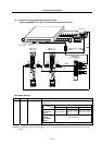
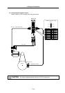
(1) Connecting the motor built-in PLG
U VW
Max. 30m
U V W
CN5
Spindle motor
MDS-C1-SP
Power cable
Option cable : CNP5
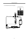
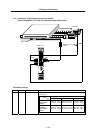
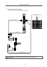
BU
BW
BV
Cooling fan terminal
block (BU,BV,BW)
Grounding terminal
Motor power terminal
block (U,V,W)
Example for 3-phase cooling fan
power supply
(Note) Either a single-phase or 3-phase power supply is used for the cooling fan.
Refer to the Spindle Motor Specifications for details.
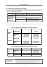
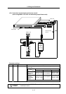
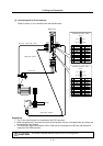
Pin No.
Detector connector : CN5
No.1
No.10
No.11
No.20
Name
RG
N15(-15V)
RA
RB
Pin
11
12
13
14
15
16
17
18
19
20
Name
LG
MOH
P15(+15V)
PA
PB
PZ
Pin
1
2
3
4
5
6
7
8
9
10
CAUTION
The shield of spindle detector cable is not FG. Do not ground.