


2. Wiring and Connection
2 - 10
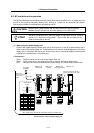
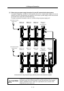
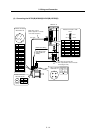
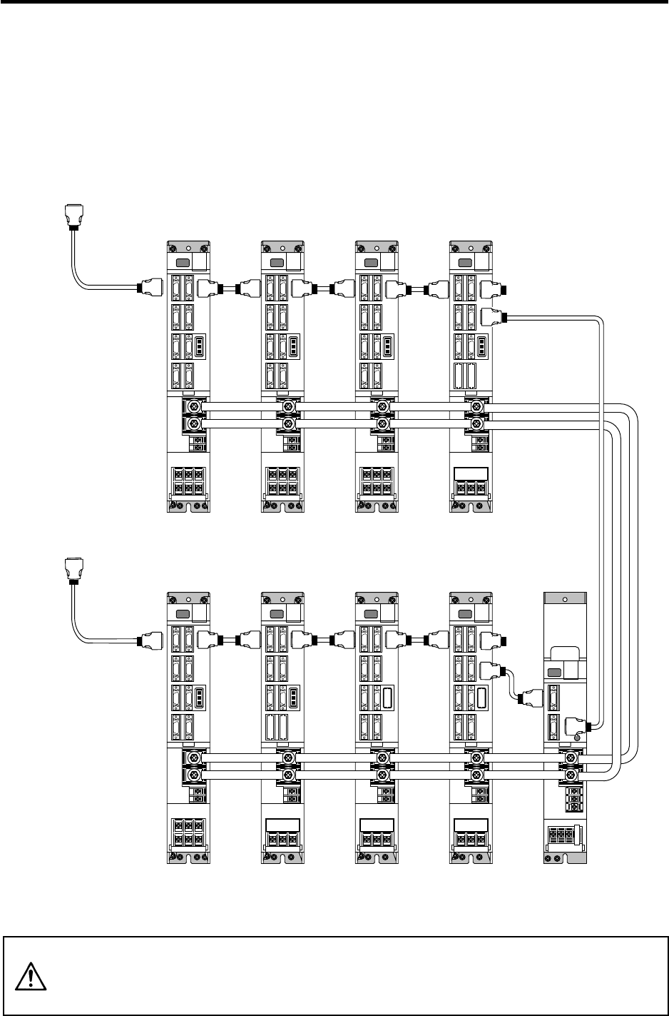
(3) When using one power supply shared unit by two NC communication bus systems
In systems employing a number of small-capacity drive units, a single power supply unit can be
shared by two NC communication bus systems. In this case, a power supply control axis must be
set for each axis of each NC communication bus.
For basic connection information, refer to "(1) When using one power supply unit".
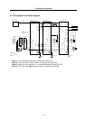
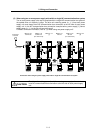
Connections when using one power supply shared by two NC communication bus systems
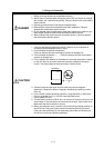
CAUTION
If the two NC communication bus systems include a spindle drive unit, connect
the power supply unit's CN4 connector to the CN4 connector of the largest-
capacity spindle drive unit. If there is no spindle drive unit, connect to the
unbalance-axis servo drive unit.
MDS-C1-SP
12th axis
(CV control axis)
MDS-C1-V1
7th axis
(CV control axis)
CN1A
Connected to the NC
(System No.1)
MDS-C1-CV
(shared)
MDS-C1-V2
1st/2nd axis
CN1B CN1A
CN1B
CN4
CN4
MDS-C1-V2
3rd/4th axis
MDS-C1-V2
5th/6th axis
CN1B
CN1A
CN1B
CN1A
MDS-C1-V2
8th/9th axis
CN1B CN1A
MDS-C1-V1
10th axis
MDS-C1-SP
11th axis
CN1A
Connected to the NC
(System No.2)
CN1B
CN1A
CN1B
CN1A
CN1B
CN4
CN9