


Contents for MDS-C1 Series SPECIFICATIONS MANUAL (BNP-C3040D)
1. Introduction
1-1 Servo/spindle drive system configuration............1-2
1-1-1 System configuration.................................................1-2
1-1-2 Unit outline type.........................................................1-3
1-2 Explanation of type..............................................1-4
1-2-1 Servomotor type........................................................1-4
1-2-2 Servo drive unit type..................................................1-8
1-2-3 Spindle motor type.....................................................1-10
1-2-4 Spindle drive unit type ...............................................1-12
1-2-5 Power supply unit type...............................................1-13
1-2-6 AC reactor type..........................................................1-14
2. Specifications
2-1 Servomotor..........................................................2-2
2-1-1 Specifications list.......................................................2-2
2-1-2 Torque characteristics ...............................................2-7
2-2 Spindle motor......................................................2-10
2-2-1 Specifications............................................................2-10
2-2-2 Output characteristics................................................2-15
2-3 Drive unit.............................................................2-20
2-3-1 Servo drive unit..........................................................2-20
2-3-2 Spindle drive unit.......................................................2-22
2-3-3 Power supply unit......................................................2-23
2-3-4 AC reactor.................................................................2-24
2-3-5 D/A output specifications for servo drive unit.............2-25
2-3-6 D/A output specifications for spindle drive unit...........2-26
2-3-7 Explanation of each part............................................2-27
2-4 Restrictions on servo control...............................2-30
2-4-1 Restrictions of electronic gear setting value...............2-30
2-4-2 Restrictions on absolute position control....................2-32
3. Characteristics
3-1 Servomotor..........................................................3-2
3-1-1 Environmental conditions...........................................3-2
3-1-2 Quakeproof level .......................................................3-2
3-1-3 Shaft characteristics..................................................3-3
3-1-4 Oil/water standards....................................................3-4
3-1-5 Magnetic brake..........................................................3-5
3-1-6 Dynamic brake characteristics...................................3-8
3-2 Spindle motor......................................................3-10
3-2-1 Environmental conditions...........................................3-10
3-2-2 Shaft characteristics..................................................3-10
3-3 Drive unit characteristics.....................................3-11
3-3-1 Environmental conditions...........................................3-11
3-3-2 Heating value.............................................................3-12
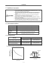
3-3-3 Overload protection characteristics............................3-13
4. Dedicated Options
4-1 Servo options ......................................................4-2
4-1-1 Battery and terminator option (mandatory selection)..4-3
4-1-2 Dynamic brake unit (MDS-B-DBU)
(mandatory selection for large capacity)....................4-5
4-1-3 Ball screw end detector .............................................4-7
4-1-4 Machine end detector................................................4-8
4-1-5 Detector conversion unit (MDS-B-HR).......................4-10
4-1-6 Signal divider unit (MDS-B-SD) .................................4-12
4-2 Spindle option.....................................................4-14
4-2-1 Magnetic sensor........................................................4-16
4-2-2 Spindle end detector
(OSE-1024-3-15-68, OSE-1024-3-15-68-8) ..............4-18
4-2-3 C-axis detector (OSE90K).........................................4-20
4-2-4 C-axis detector (MBE90K).........................................4-22
4-2-5 C-axis detector (MHE90K).........................................4-23
4-2-6 Spindle end PLG (MXE128/180/256/512)..................4-24
4-2-7 Detector conversion unit (MDS-B-PJEX)...................4-28
4-3 Cables and connectors.......................................4-30
4-3-1 Cable connection diagram.........................................4-30
4-3-2 List of cables and connectors....................................4-31
5. Peripheral Devices
5-1 Selecting the wire size........................................5-2
5-2 Selection the AC reactor, contactor
and no-fuse breaker........................................... 5-5
5-2-1 Standard selection.....................................................5-5
5-2-2 Selection when a contactor is shared........................5-6
5-3 Circuit protector ..................................................5-7
5-4 Circuit protector ..................................................5-8
5-5 Noise filter...........................................................5-9
5-6 Surge absorber...................................................5-10
5-7 Speedometer and load meter .............................5-11
5-8 Cable for peripheral control ................................ 5-12
5-8-1 Cable for external emergency stop............................5-12
5-8-2 Cable for servomotor magnetic brake........................5-13
Appendix 1. Outline Dimension Drawings
Appendix 1-1 Servomotor outline dimension drawings
............................................................A1-2
Appendix 1-1-1 HC Series..................................................A1-2
Appendix 1-1-2 HA Series..................................................A1-8
Appendix 1-2 Outline dimension drawings
of spindle motor................................... A1-12
Appendix 1-2-1 SJ Series...................................................A1-12
Appendix 1-2-2 SJ-V Series................................................A1-15
Appendix 1-2-3 SJ-VS Series.............................................A1-25
Appendix 1-2-4 SJ-PMF Series (IPM motor).......................A1-27
Appendix 1-3 Unit outline dimension drawings......... A1-28
Appendix 1-3-1 Servo/spindle drive unit .............................A1-28
Appendix 1-3-2 Power supply unit ......................................A1-37
Appendix 1-3-3 AC rector...................................................A1-41
Appendix 2. Table and Connector Specifications
Appendix 2-1 Selection of cable ...............................A2-2
Appendix 2-1-1 Cable wire and assembly...........................A2-2
Appendix 2-1-2 Flexible conduits........................................A2-4
Appendix 2-2 Cable connection diagram..................A2-6
Appendix 2-3 Connector outline dimension drawings
............................................................A2-12
Appendix 3. Selection
Appendix 3-1 Selecting the servomotor series .........A3-2
Appendix 3-1-1 Motor series characteristics.......................A3-2
Appendix 3-1-2 Servomotor precision.................................A3-3
Appendix 3-2 Selection of servomotor capacity........A3-4
Appendix 3-2-1 Load inertia ratio........................................A3-4
Appendix 3-2-2 Short time characteristics...........................A3-4
Appendix 3-2-3 Continuous characteristics.........................A3-5
(Note) This is the content for SPECIFICATION MANUAL version D. The structure of section and page number may be different
other than version D.