


5. Spindle Adjustment
5 - 57
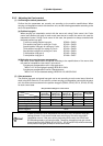
5-3-6 Adjusting the spindle synchronous control
(1) Confirming the default parameters
Confirm that the parameters are correctly set according to the machine specifications. The
parameters are set with the following conditions for spindles used for synchronous control.
(a) Position loop gain
The same value must be set for the spindle drive units used for synchronous control.
Spindle synchronous position loop gain : SP010
Spindle synchronous position loop gain 2 : SP189
Spindle synchronous position loop gain 3 : SP190
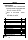
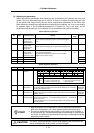
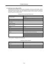
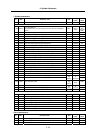
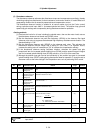
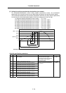
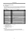
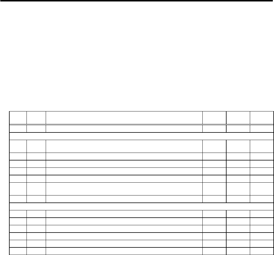
<Spindle parameters>
No. Abbr. Parameter name Unit
Setting
range
Standard
value
SP010 PGS Spindle synchronization position loop gain rad/s 1 to 100 15
SP177 SPECS* Spindle synchronous specifications HEX
0000 to
FFFF
0000
SP178 VGSP* Spindle synchronous speed loop gain proportional term 0 to 1000 63
SP179 VGSI* Spindle synchronous speed loop gain integral term 0 to 1000 60
SP180 VGSD* Spindle synchronous speed loop gain delay advance term 0 to 1000 15
SP181 VCGS* Spindle synchronous Target value of variable speed loop proportional gain % 0 to 100 100
SP182 VCSS*
Spindle synchronous Change starting speed of variable speed loop
proportional gain
r/min 0 to 32767 0
SP183 SYNV Spindle synchronous Sync matching speed r/min 0 to 1000 20
SP185 SINP Spindle synchronous In-position width 1/16 deg 1 to 2880 16
SP186 SODR* Spindle synchronous Excessive error width (1pulse=0.088deg) pulse 0 to 32767 32767
SP187 IQGS* Spindle synchronous Current loop gain magnification 1 % 0 to 1000 100
SP188 IDGS* Spindle synchronous Current loop gain magnification 2 % 0 to 1000 100
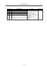
SP189 PG2S Spindle synchronous Position loop gain 2 rad/s 0 to 999 0
SP190 PG3S Spindle synchronous Position loop gain 3 rad/s 0 to 999 0