


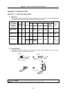
Appendix 1. Cable and Connector Specifications
A1 - 6
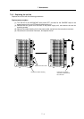
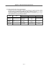
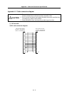
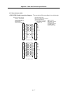
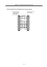
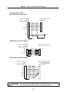
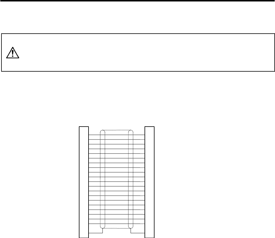
Appendix 1-2 Cable connection diagram
CAUTION
1. Do not mistake the connection when manufacturing the detector cable.
Failure to observe this could lead to faults, runaway or fires.
2. Do not connect anything to pins unless otherwise particularly specified when
manufacturing a cable. (Leave OPEN)
3. Contact Mitsubishi when manufacturing a cable longer than 30m.
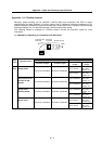
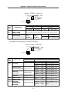
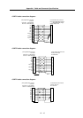
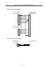
(1) NC bus cable
<SH21 cable connection diagram>
Drive unit side connector
Connector: 10120-3000VE
Shell kit: 10320-52F0-008
Drive unit side connector
Connector: 10120-3000VE
Shell kit: 10320-52F0-008
1
11
2
12
3
13
4
14
5
15
6
16
7
17
8
18
9
19
10
20
PE
1
11
2
12
3
13
4
14
5
15
6
16
7
17
8
18
9
19
10
20
PE
FG