


2. Wiring and Connection
2 - 3
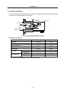
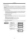
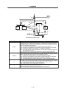
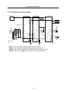
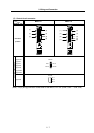
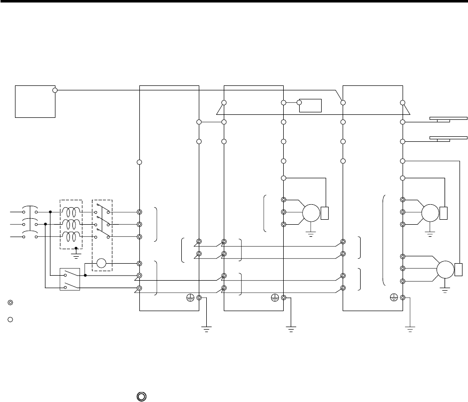
2-1 Part system connection diagram
MC1
Mitsubishi CNC
SV1,2
(CSH21)
External emergency
stop input
T
S
R
Contacto
r
No-fuse
breaker
Ground
: Main circuit
: Control circuit
CN1A
CN23
CN4
CN9
L1
L2
L3
L11
TE3
TE1
CN9
CN1B
L+
L-
U
V
W
CN6
CN5
TE1
PLG
Spindle drive unitPower supply unit
Spindle
motor
CN4
TE3
TE2
L+
L-
L11
L21
TE2
AC
reactor
Ground
Ground
L21
CN8
CN7
CN1A
CN4
CN9
CN20
CN1B
MU
MV
MW
CN2L
CN2M
LU
LV
LW
TE1
Motor end
detector
Motor end
detector
Battery unit
Servo drive unit
Servo
motor
Servo
motor
Tool end detecto
r
Tool end detecto
r
TE3
TE2
L+
L-
L11
L21
Ground
CN3M
CN3L
CN1A
MC
Breaker
SH21 cable
SH21 cable
(Note 1) The total length of the SH21 cable must be within 30m.
(Note 2) The connection method will differ according to the used motor.
(Note 3) When not using a battery unit, connect the terminal connector (R-TM).
(Note 4) The main circuit (
) and control circuit ({) are safely separated.