


2. Wiring and Connection
2 - 40
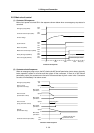
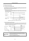
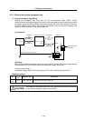
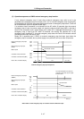
(3) Operation sequences when an emergency stop occurs
The motor brake control output operation when an emergency stop occurs differs according to the
motor deceleration stop method. Refer to section "4-5 Setting for emergency stop" for details on the
operation sequences for each stop method.
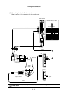
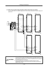
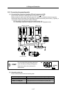
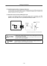
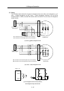
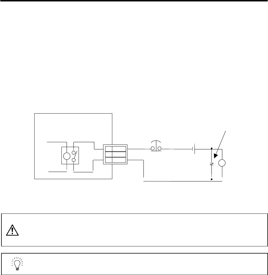
(4) Motor brake control connector (CN20) output circuit
As shown in the illustration below, an external power supply circuit is controlled by the CN20
connector output. Dynamic brake unit is controlled simultaneously for large-capacity drive unit
(MDS-C1-V1-110/150). Refer to "2-6-2 Dynamic brake unit wiring" for details.
(Unit internal relay specification: 5A 30Vdc/8A 250Vac)
CAUTION
1. Always install a surge absorber near the motor's brake terminal to eliminate
noise and protect the contacts.
2. The brakes cannot be released just by connecting the CN20 and motor brake
terminal. 24VDC must be supplied.
POINT
To ensure safety in an emergency, make sure that the magnetic brakes are
applied in sequence with the emergency stop switch.
A
lways install a surge
absorber
Brake
MDS-C1-V1/V2
3 MBR2
2
DBR
1 MBR1
CN20
24VDC
Surge
absorber
Emergenc
y
stop switch