


3. Setup
3 - 104
3-6 Initial adjustment of the spindle PLG
3-6-1 Adjusting the PLG installation
The PLG (spindle motor speed detector) mounted on the
Mitsubishi framed spindle motor is shipped from Mitsubishi
in the adjusted state. If there are no particular problems,
carry out automatic adjustment "3-6-2 Automatic
adjustment of Z phase" and "3-6-3 Automatic adjustment of
motor end PLG" according to the spindle system.
When using the spindle end PLG for simple C-axis control
or the built-in spindle, the PLG detector is installed by the
user, so the PLG sensor's gap and output signal must be
adjusted with the following procedures. After installing and
adjusting these, carry out automatic adjustment of the PLG
according to each system.
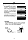
Install the PLG and then adjust following the procedures on
the right. The output signal waveform can be retrieved from
the check terminal on the PCB. Measure the waveform with
an oscilloscope. The A/B phase output signal and the Z
phase pulse width can be adjusted with the volume (VR1 to
VR5) on the PCB. (The pulse width has been adjusted at
shipment, and normally does not need to be adjusted.)
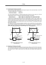
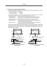
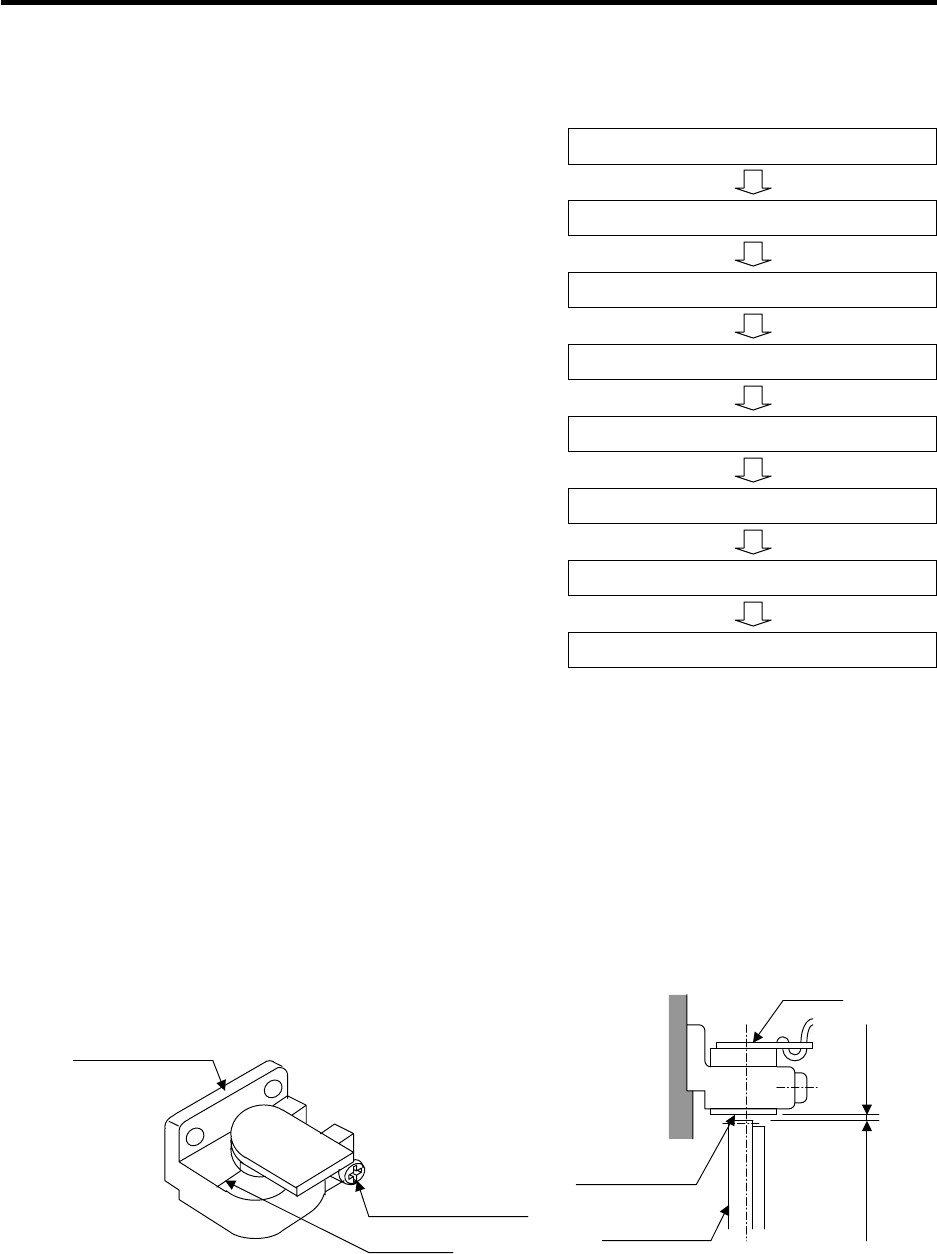
(1) Checking the gap
Check that the gap between the sensor detection surface and detection gear circumference is
within 0.15±0.01mm as shown below. The gap is adjusted before shipment, but an error could
occur due to the effect of the dimensional difference of the notched fitting section provided for
installation, or the dimensional difference of the detection gears' outer diameter. If deviated from
the above range, adjust the gap following the section "(2) Adjusting the gap".
Sensor section Gap with detection gear
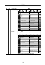
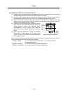
(1) Checking the gap
(2) Adjusting the gap
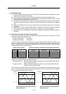
(3) Checking the A and B phase output signal
(4) Adjusting the A and B phase output signal
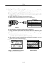
(5) Checking the Z phase pulse width
(6) Adjusting the Z phase pulse width
(7) Checking the Z phase and A phase difference
(8) Adjusting the Z phase and A phase difference
Flow of PLG installation and adjustment
Senso
r
Detection gear
circumference
Ga
p
0.15±0.01mm
Detection gear
Sensor detection
surface
Markin
g
line
Sensor installation
seat
Sensor fixing screw