


6. Troubleshooting
6 - 27
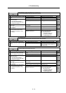
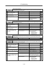
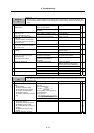
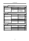
Alarm No.
51
Overload 2
With the servo, a current command exceeding 95% of the unit's maximum current continued for one
second or more. With the spindle, a load exceeding the continuous rating continued for 30 minutes or
more.
Investigation details Investigation results Remedies SV SP
The alarm occurred after ready ON
before operation starts.
Investigate item 2. 1 Did the alarm occur immediately after
READY ON?
The alarm occurred after normal
operation.
Investigate item 5.
{
The voltage is not supplied. Correctly supply the PN voltage. 2 Check that the PN voltage is supplied
to the drive unit.
Is the CHARGE lamp ON?
Approx. 300V is correctly supplied. Investigate item 3.
{
The connections are incorrect. Connect correctly. 3 Check the motor power cable (U, V,
W phases).
The power cable is not connected.
Is the cable connected to the motor
for another axis?
The connections are correct. Investigate item 4.
{
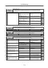
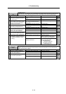
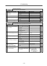
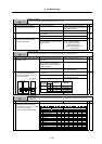
The connections are incorrect. Connect correctly. 4 Check the detector cable connection.
Is the cable connected to the motor
for another axis?
The connections are correct. Investigate item 5.
{
The machine has collided. Check the machining program and
soft limit settings.
5 Check whether the machine has
collided.
The machine has not collided. Investigate item 6.
{
The current is saturated during
acceleration/deceleration.
Increase the acceleration/
deceleration time constant.
6 Check whether the current value on
the NC Servo Monitor screen is
saturated during
acceleration/deceleration.
The current value during
acceleration/deceleration is
appropriate.
Investigate item 7.
{
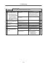
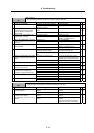
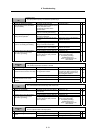
The FB signal is abnormal. Replace the detector.
(With the absolute position system,
the zero point must be established.)
7 Check the detector FB.
The FB signal is normal. Replace the drive unit.
{
The load is large. Lower the load. 8 Check the load meter value.
The load is not large. Investigate item 9.
{
There is a problem. Adjust the PLG output waveform. 9 Check the PLG output waveform.
Normal Replace the drive unit.
{
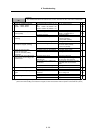
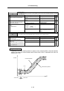
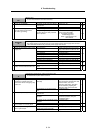
Alarm No.
52
Excessive error 1
The difference between the motor's actual position at servo ON and the theoretical position exceeded
the setting value.
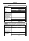
Investigation details Investigation results Remedies SV SP
The excessive error detection width is
too small.
Servo standard value:
SV023 =
RAPID
60
×
PGN1
÷ 2
For the spindle, a value larger than
the droop amount:
Droop amount =
Spindle rotation speed
×
No. of pulses
60
×
position loop gain
Set appropriate values. 1 Check the excessive error detection
width.
SV023 (Servo)
SP102 (Orientation control)
SP154, SP155 (C-axis control)
SP177/bitD, SP186 (Spindle
synchronous control)
SP193/bitD, SP218 (Synchronous
tap)
Appropriate values are set. Investigate item 2.
{ {
The polarity is reversed. Correctly set the parameters. 2 Check the position detector polarity.
SV017/bit4 (Servo)
SP097/bit5 (Orientation control)
SP129/bit5 (C-axis control)
SP177/bit5 (Spindle synchronous
control)
SP193/bit5 (Synchronous tap
control)
Normal. Investigate item 3.
{ {
3 Check the alarm No. "51" items.
{ {