


2. Wiring and Connection
2 - 42
2-7 Peripheral control wiring
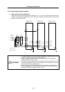
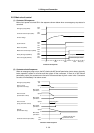
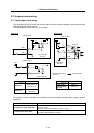
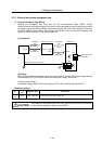
2-7-1 Input/output circuit wiring
The input/output circuit to control the external signal such as external emergency stop input and relay
changeover signal output is wired.
The input/output circuit for each unit is as follows.
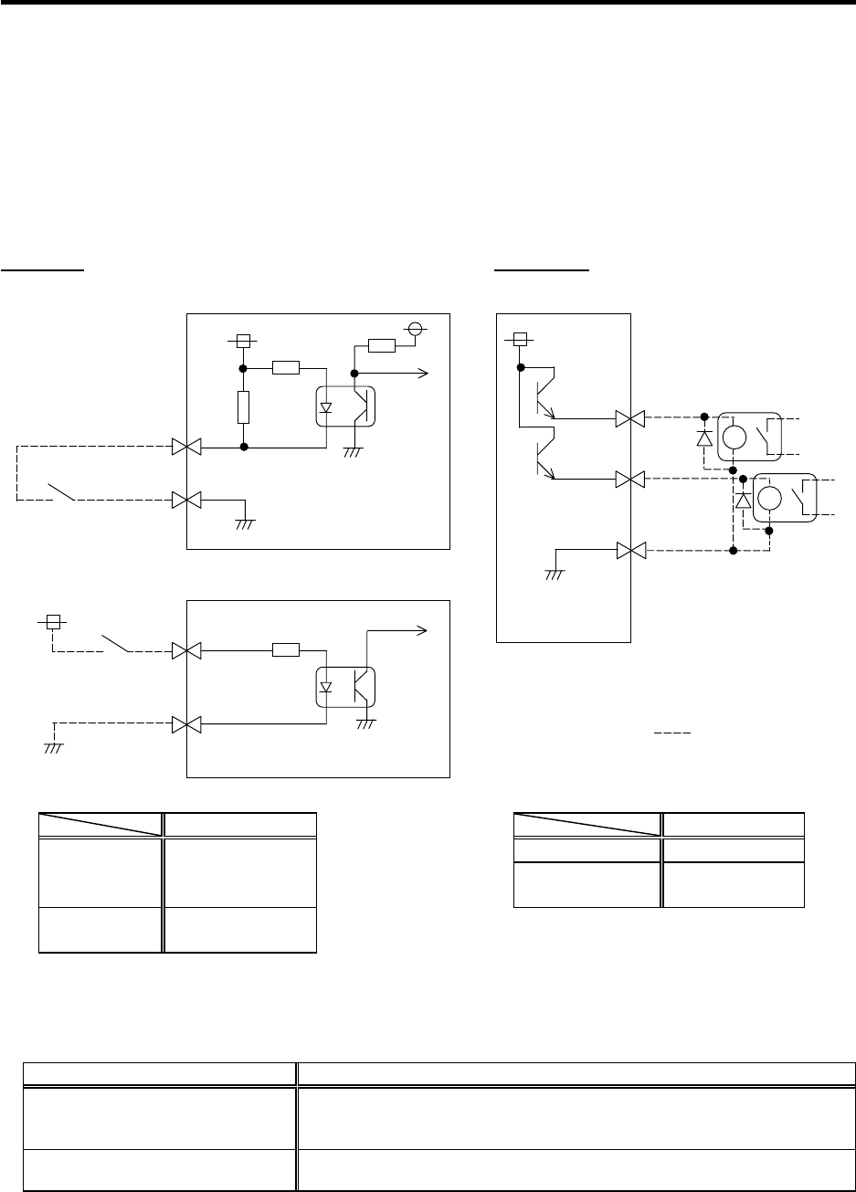
Input circuit Output circuit
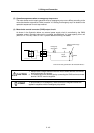
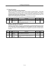
For a switch or relay to be wired, use a switch or relay that satisfies the input/output (voltage, current)
conditions.
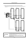
Interface name Selection example
For digital input signal (CN23,CN9)
Use a minute signal switch which is stably contacted and operated even with low
voltage or current
<Example> OMRON: G2A, G6B type, MY type, LY type
For digital output signal (CN9)
Use a compact relay operated with rating of 24VDC, 50mA or less.
<Example> OMROM: G6B type, MY type
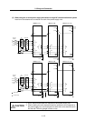
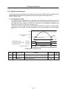
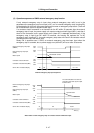
Input condition
Output condition
Output voltage 24VDC ±5%
Switch ON
18VDC to 25.2VDC
9mA or more
Tolerable output
current Io
50mA or less
Switch OFF
4VDC or less
2mA or less
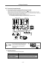
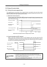
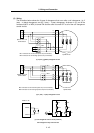
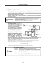
20
10
CN9 connector
Servo/spindle
drive unit
Switch
33.3k
24V
10k
1
3
CN23 connector
Power supply unit
Switch
24V
2k
Servo/spindle
drive unit
8
10
CN9 connector
18
MPO1
MPO2
MPI1
24G
24G
Relay, etc.
24V
The part indicated by the " " must be prepared
by the user.