


5. Spindle Adjustment
5 - 37
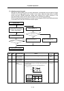
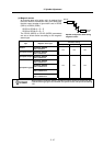
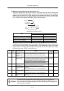
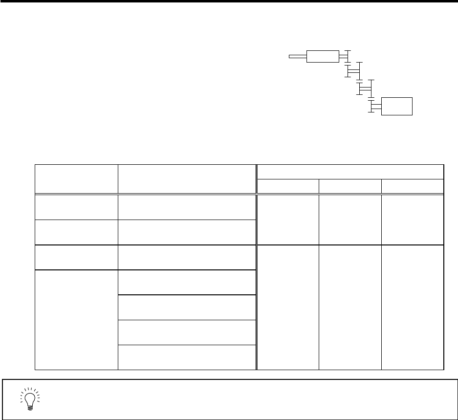
(c) Magnetic sensor
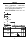
An accurate gear ratio (pulley ratio) is required from
the motor shaft to the detector rotary axis. Make sure
that the correct number of gear teeth is set in SP025
(GRA1) to SP032 (GRB1).
SP025 to SP028=A × C × E
SP029 to SP032=B × D × F
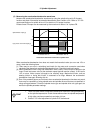
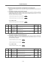
The SP123 (MGD0) to SP125 (MGD2) parameters
are set as shown below according to the magnetic
sensor type.
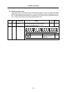
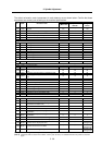
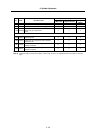
Parameter setting
Type Magnetic sensor type
SP123 (MGD0) SP124 (MGD1) SP125 (MGD2)
Standard
MAGNETIC SENSOR
BKO-C1810H01-3
High-speed standard
MAGNETIC SENSOR
BKO-C1730H01.2.6
542 768 384
High-speed compact
MAGNETIC SENSOR
BKO-C1730H01.2.9
MAGNETIC SENSOR
BKO-C1730H01.2.41
MAGNETIC SENSOR
BKO-C1730H01.2.42
MAGNETIC SENSOR
BKO-C1730H01.2.43
High-speed ring type
MAGNETIC SENSOR
BKO-C1730H01.2.44
500 440 220
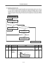
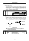
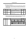
POINT
When using the magnetic sensor, orientation control cannot be carried out with
a machine having a gear ratio between the spindle motor and spindle exceeding
1:31.
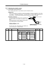
S
p
indle
Spindle
moto
r
A
B C
D E
F
Spindle configuration when using
magnetic sensor