


5. Spindle Adjustment
5 - 3
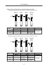
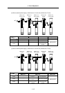
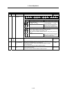
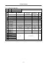
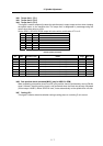
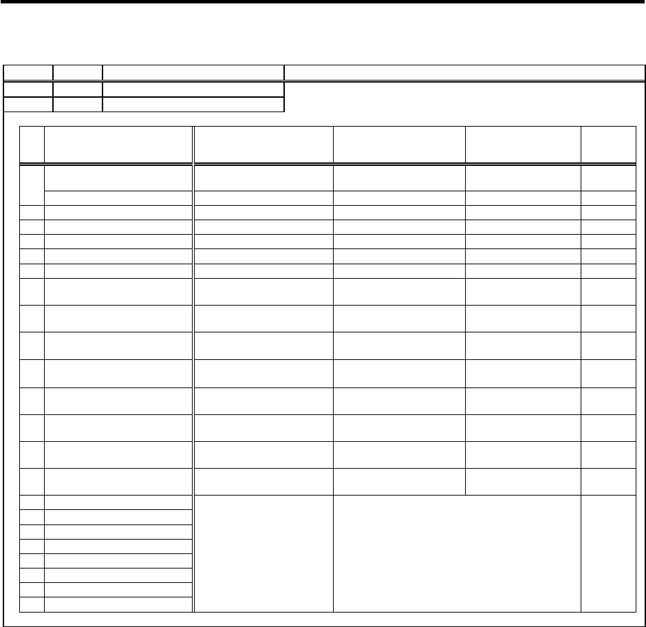
5-1-2 Setting the output data
No. Abbr. Parameter name Explanation
SP253 DA1NO
D/A output channel 1 data No.
Input the No. of the data to be output to each D/A output channel.
SP254 DA2NO
D/A output channel 2 data No.
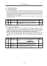
No. Output data Original data unit
Output magnification
standard setting value
(SP255, SP256)
Output unit for
standard setting
Output
cycle
ch1: Speedometer output 10V=max. speed (Zero=0V) 0
Depends on maximum
speed
3.55ms
0
ch2: Load meter output 10V=120% load (Zero=0V) 0 30-minute rating 12%/V 3.55ms
1 –
2 Current command Rated 100%=4096 8 30-minute rating 20%/V 3.55ms
3 Current feedback Rated 100%=4096 8 30-minute rating 20%/V 3.55ms
4 Speed feedback r/min 13 500rpm/V 3.55ms
5 –
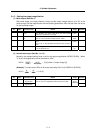
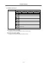
6
Position droop
(lower order 16bit)
0.001deg=64 10 (10.24) 0.01deg/V 888µs
7
Position droop
(higher order 16bit)
1deg=(64000÷65536)
671 10deg/V 888µs
8
Feedrate (F∆T)
(lower order 16bit)
0.001deg=64
173
(at 3.5ms communication)
10deg/min/V 888µs
9
Feedrate (F∆T)
(higher order 16bit)
1deg=(64000÷65536)
629
(at 3.5ms communication)
500rpm/V 888µs
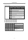
10
Position command
(lower order 16bit)
0.001deg=64 10 (10.24) 0.01deg/V 888µs
11
Position command
(higher order 16bit)
1deg=(64000÷65536)
19 (18.64) 360deg/V 888µs
12
Position FB
(lower order 16bit)
0.001deg=64 10 (10.24) 0.01deg/V 888µs
13
Position FB
(higher order 16bit)
1deg=(64000÷65536)
19 (18.64) 360deg/V 888µs
80 Control input 1
81 Control input 2
82 Control input 3
83 Control input 4
84 Control output 1
HEX Bit correspondence 3.55ms
85 Control output 2
86 Control output 3
87 Control output 4