


3. Setup
3 - 70
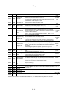
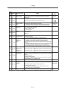
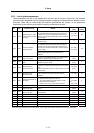
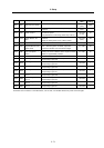
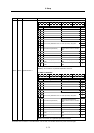
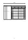
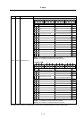
3-5-2 List of spindle parameters
These parameters are sent to the spindle drive unit when the NC power is turned ON. The standard
parameters are designated with the "Spindle parameter setting list" enclosed when the spindle motor is
delivered. There may be cases when the machine specifications are unclear, so the parameters
determined by the machine specifications should be confirmed by the user.
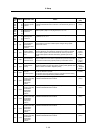
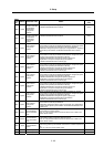
No. Abbr. Parameter name Details
Setting range
(Unit)
Standard
setting
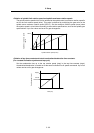
<For MDS-C1-SP/SPH/SPM>
The orientation time will be shorter when the value is
increased, and the servo rigidity will increase. On the
other hand, the vibration will increase, and the machine
will sway easily.
0 to 1000
(0.1 rad/s)
100
SP001 PGM
Magnetic sensor, motor
PLG orientation position
loop gain
<For MDS-C1-SPX/SPHX>
Not used. Set "0".
0 0
<For MDS-C1-SP/SPH/SPM>
The orientation time will be shorter when the value is
increased, and the servo rigidity will increase. On the
other hand, the vibration will increase, and the machine
will sway easily.
SP002 PGE
Encoder orientation
position loop gain
<For MDS-C1-SPX/SPHX>
Set the position loop gain for spindle end PLG
orientation.
0 to 1000
(0.1 rad/s)
100
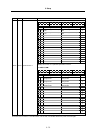
SP003 PGC
Position gain during
C-axis non-cutting
Set the position loop gain for the C-axis non-cutting mode.
During non-cutting (rapid traverse, etc.) with the C axis
control, this position loop gain setting is valid.
0 to 100
(rad/s)
15
SP004 OINP
Orientation in-position
width
Set the position error range in which an orientation
completion signal is output.
1 to 2880
(1/16°)
16
SP005 OSP*
Orientation mode
speed clamp value
Set the motor speed limit value to be used when the
speed loop is changed to the position loop in orientation
mode.
When this parameter is set to "0", SP017 (TSP) becomes
the limit value.
0 to 32767
(r/min)
0
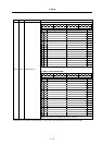
SP006 CSP
Orientation mode
deceleration rate
As the set value is larger, the orientation time becomes
shorter. However, the machine becomes likely to
overshoot.
1 to 1000 20
SP007 OPST
Position shift amount for
orientation
Set the stop position for orientation.
(1) Motor PLG and spindle end detector
Set a value obtained by dividing 360° by 4096.
(2) Magnetic sensor orientation
Divide -5°C to +5° by 1024, and set 0° as "0".
(1)
0 to 4095
(2)
-512 to 512
0
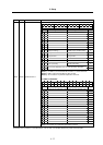
SP008
Not used. Set
"0".
0 0
SP009 PGT
Synchronous tap
position loop gain
Set the spindle position loop gain for synchronous
tapping.
1 to 100
(rad/s)
15
SP010 PGS
Spindle synchronization
position loop gain
Set the spindle position loop gain for spindle
synchronization.
1 to 100
(rad/s)
15
SP011 Not used. Set "0". 0 0
SP012 Not used. Set "0". 0 0
SP013 Not used. Set "0". 0 0
SP014 Not used. Set "0". 0 0
SP015 Not used. Set "0". 0 0
SP016 Not used. Set "0". 0 0
Parameters with an asterisk * in the abbreviation, such as OSP*, are validated with the NC power turned ON again.