


4. Servo Adjustment
4 - 2
CAUTION
"Chapter 4 Servo adjustment" explains the methods when controlling with the
high-gain specifications.
4-1 D/A output specifications for servo drive unit
The MDS-C1-V1/V2 servo drive unit has a function to D/A output the various control data.
The servo adjustment data required for setting the servo parameters to match the machine can be D/A
output. Measure using a hi-coder, oscilloscope, etc.
4-1-1 D/A output specifications
Item Explanation
No. of channels 2ch
Output cycle 888µs (min. value)
Output precision 8bit
Output voltage range 0V to 2.5V (zero) to +5V
Output magnification
setting
±1/256 to ±128-fold
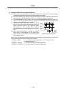
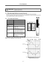
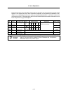
Output pin
CN9 connector
MO1 = Pin 9
MO2 = Pin 19
GND = Pins 1, 11
Function
Phase current feedback output function
L axis U phase current FB : Pin 7
L axis V phase current FB : Pin 17
M axis U phase current FB : Pin 6
M axis V phase current FB : Pin 16
Others
The D/A output for the 2-axis unit
(MDS-C1-V2) is also 2ch. When using
the 2-axis unit, set -1 for the output
data (SV061, 62) of the axis that is not
to be measured.
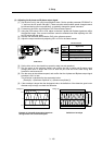
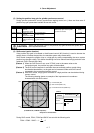
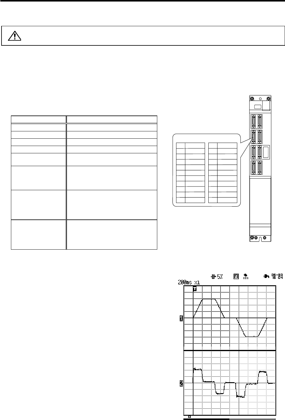
With the MDS-C1-V1/V2 Series, there is a 2.5V offset voltage (2.5V when data is 0), so the zero level
position must be adjusted on the hi-corder side.
+2.5 [V]
0 [V]
Speed FB
Single
shot
Current FB
+2.5 [V]
0 [V]
+5 [V]
+5 [V]
Scroll
Memory
Example of D/A output waveform
MO19
Name
LG
LUIFB
MUIFB
2
5
1
Pin
6
4
3
10
7
8
CN9 connector
MO2 19
Name
LG
LVIFB
MVIFB
12
15
11
Pin
16
14
13
20
17
18