


6. Troubleshooting
6 - 9
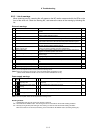
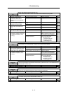
6-2-2 List of warnings
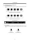
When a warning occurs, a warning No. will appear on the NC monitor screen and with the LEDs on the
front of the drive unit. Check the warning No., and remove the cause of the warning by following this
list.
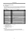
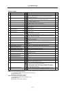
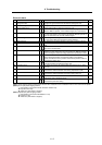
Drive unit warnings
No. Alarm name Warning details Reset
90 Detector, initial communication error Initial communication with the absolute position linear scale was not
possible.
PR
91 Detector, communication error An error was detected in the communication with the detector for the
absolute position detection system.
*
92 Detector, protocol error An error was detected in the data for the absolute position detection system. *
93 Initial absolute position fluctuation The position data fluctuated when creating the initial absolute position. PR
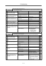
96 MP scale feedback error An excessive deviation was detected in the motor end detector and MP
scale feedback data for the MP scale absolute position detection system.
*
97 MP scale offset error An error was detected in the offset data received from the MP scale for the
MP scale absolute position detection system.
PR
9E Absolute position detector, multi-
rotation counter error
An error was detected in the multi-rotation counter for the absolute position
detector. The absolute position cannot be compensated.
*
9F Battery voltage drop The voltage of the battery supplying to the absolute position detector has
dropped. The absolute position data is held.
*
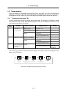
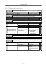
A8 Turret indexing error warning The commanded turret indexing position shift amount is not within the
specified range.
*
A9 Orientation feedback error warn Retrying during an orientation feedback error. *
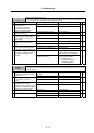
E1 Overload warning The overload detection level is 80% or more. *
E3 Absolute position counter warning A deviation was detected in the absolute position data and absolute position
data.
*
E4 Parameter error warning A parameter exceeding the setting range was set. *
E6 Control axis removal warning Control axis removal was commanded. *
E7 CNC emergency stop Emergency stop was input from the NC. *
(Note 1) Servo and spindle motor do not stop when the warning occurs.
(Note 2) When an emergency stop is input, servo and spindle motor decelerate to a stop.
(When SV048, SV055 or SV056 is set for servo and when SP038/bit 0=1is set.)
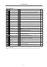
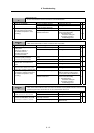
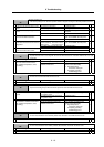
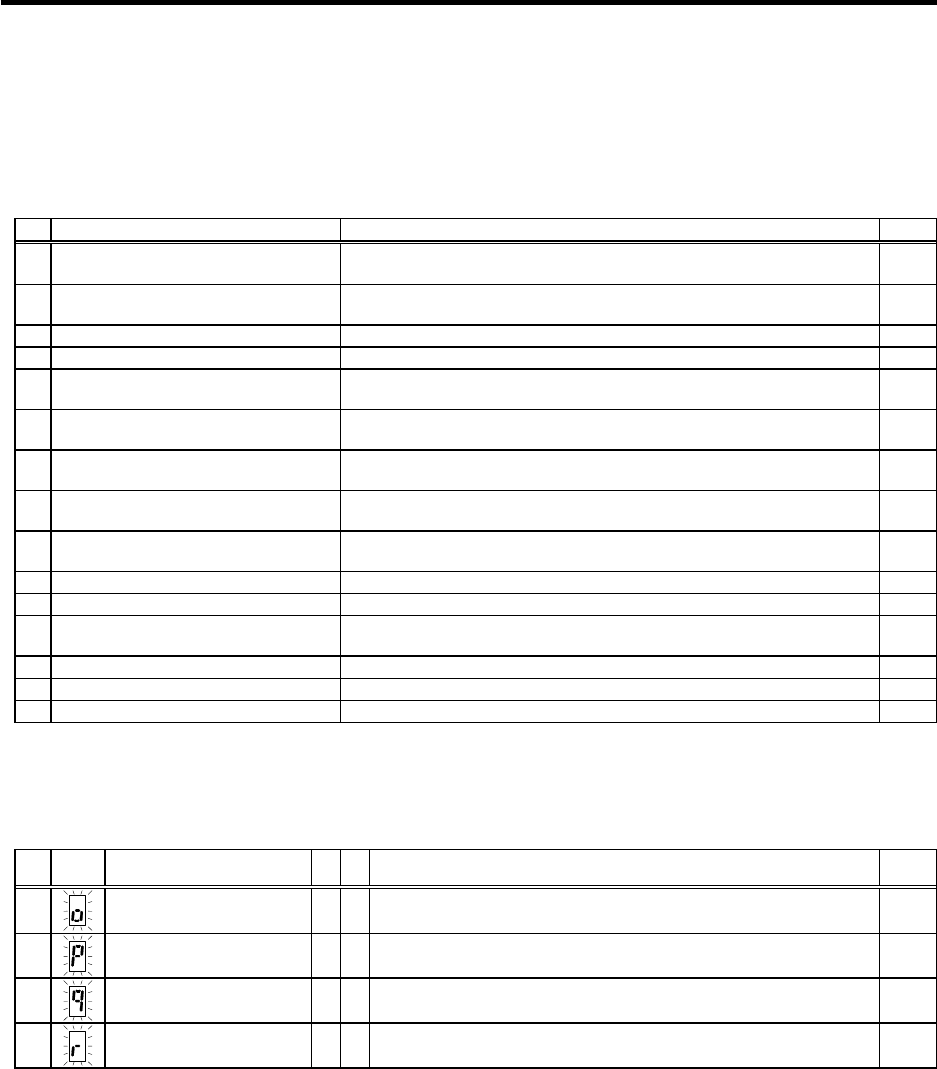
Power supply warnings
No.
LED
display
Alarm name CV CR Warning details Reset
E8
Auxiliary regeneration
frequency over
{
Regeneration at the power supply performance limit is occurring
frequently.
*
E9
Instantaneous power failure
warning
{
An instantaneous power failure occurred. NR
EA
External emergency stop
{
The external emergency stop signal was input. *
EB
Over-regeneration warning
{
The over-regeneration level is 80% or more. *
(Note) Servo and spindle motor do not stop when the warning occurs.
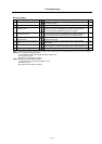
Resetting methods
* : Automatically reset once the cause of the warning is removed.
NR : Reset with the NC RESET button. This warning can also be reset with the PR and AR resetting conditions.
PR : Reset by turning the NC power ON again. This warning can also be reset with the AR resetting conditions.
When the control axis is removed, this warning can be reset with the NC RESET button. (Excluding warning 93.)