


3. Setup
3 - 62
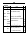
Standard specifications
No. Abbrev. Parameter name Explanation
Setting range
(Unit)
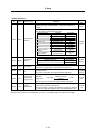
SV051
DFBT
Dual feed back
control time
constant
Set the control time constant in dual feed back.
When “0” is set, the actual value that is set is 1ms.
The higher the time constant is, the closer it gets to the semi-closed control,
so the limit of the position loop gain is raised.
0 to 9999
(ms)
SV052
DFBN
Dual feedback
control dead zone
Set to “0” as a standard.
Set the dead zone in the dual feedback control.
0 to 9999
(µm)
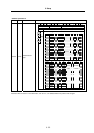
SV053 OD3
Excessive error
detection width in
special control
Set the excessive error detection width when servo ON in a special control
(initial absolute position setting, stopper control, etc.).
If “0” is set, excessive error detection won’t be performed.
0 to 32767
(mm)
SV054 ORE
Overrun detection
width in closed loop
control
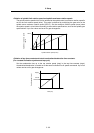
Set the overrun detection width in the full-closed loop control.
If the gap between the motor end detector and the linear scale (tool end
detector) exceeds the value set by this parameter, it is judged to be overrun
and Alarm 43 will be detected.
When “-1” is set, the alarm detection won’t be performed. When “0” is set,
overrun is detected with a 2mm width.
-1 to 32767
(mm)
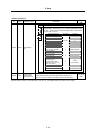
SV055
EMGx
Max. gate off delay
time after
emergency stop
Set a length of time from the point when the emergency stop is input to the
point when READY OFF is compulsorily executed.
Normally, set the same value as the absolute value of SV056.
In preventing the vertical axis from dropping, the gate off is delayed for the
length of time set by SV048 if SV055’s value is smaller than that of SV048.
0 to 20000
(ms)
SV056 EMGt
Deceleration time
constant at
emergency stop
Set the time constant used for the deceleration control at emergency stop.
Set a length of time that takes from rapid traverse rate (rapid) to stopping.
Normally, set the same value as the rapid traverse acceleration/deceleration
time constant.
When executing the synchronous operation, put the minus sign to the
settings of both of the master axis and slave axis.
-20000 to
20000
(ms)
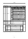
SV057 SHGC
SHG control gain
When performing the SHG control, set this with S003 (PGN1) and SV004
(PGN2).
When not performing the SHG control, set to “0”.
0 to 999
(rad/s)
SV058 SHGCsp
SHG control gain in
spindle
synchronous control
Set this with SV049 (PGN1sp) and SV050 (PGN2sp) if you wish to perform
the SHG control in the synchronous tapping control.
When not performing the SHG control, set to “0”.
0 to 999
(rad/s)
SV059 TCNV
Collision detection
torque estimating
gain
Set the torque estimating gain when using the collision detection function.
After setting as SV035/bitF(clt)=1 and performing acceleration/deceleration,
set the value displayed in MPOS of the NC servo monitor screen.
Set to “0” when not using the collision detection function.
-32768 to
32767
SV060 TLMT
Collision detection
level
When using the collision detection function, set the collision detection level
during the G0 feeding.
If “0” is set, none of the collision detection function will work.
0 to 999
(Stall [rated]
current %)
SV061 DA1NO
D/A output channel
1 data No.
SV062 DA2NO
D/A output channel
2 data No.
Input the data number you wish to output to D/A output channel.
In the case of MDS-C1-V2, set the axis on the side to which the data will not
be output to “-1”.
-1 to 127
SV063 DA1MPY
D/A output channel
1 output scale
SV064 DA2MPY
D/A output channel
2 output scale
Set the scale with a 1/256 unit.
When “0” is set, output is done with the standard output unit.
-32768 to
32767
(Unit: 1/256)
SV065
Not used. Set to "0".
0
Parameters with an asterisk * in the abbreviation, such as PC1*, are validated with the NC power turned ON again.